Access Control/Initialization: Difference between revisions
Techsupport (talk | contribs) Created page with "<div class="lm-banner">File:LuminysMainPageBanner2.png</div> = <div class="center">Coming soon</div> =" |
Techsupport (talk | contribs) No edit summary |
||
| Line 1: | Line 1: | ||
<div class="lm-banner">[[File:LuminysMainPageBanner2.png]]</div> | <div class="lm-banner">[[File:LuminysMainPageBanner2.png]]</div> | ||
= <div class="center">Coming soon</ | = <div class="center">Access Control Initialization and Basic Setup</div> = | ||
===Description=== | |||
This tutorial will go over how to initialize access control and some basic setup. | |||
===Prerequisites=== | |||
* Access control powered and connected on local network. | |||
===Video Instructions=== | |||
<!--<embedvideo service="youtube">Coming soon</embedvideo>--> | |||
Coming soon | |||
===Step by Step Instructions=== | |||
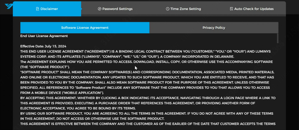
1. Open a web browser and input the IP address of the access control system into the address bar. Press Enter to access the system's web GUI. | |||
[[File:Access_Control_Initialization_1.png|1000px|link=https://wiki.luminyscorp.com/images/2/22/Access_Control_Initialization_1.png]] | |||
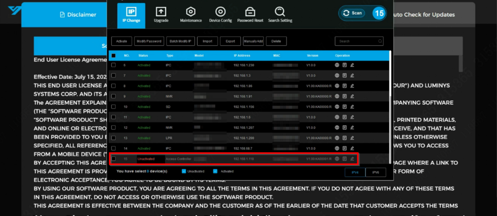
2. The LumiUtility software can also be used to initialize the access control system. Both methods offer efficient options for system setup and management, allowing flexibility based on specific requirements. | |||
[[File:Access_Control_Initialization_2.png|1000px|link=https://wiki.luminyscorp.com/images/f/fa/Access_Control_Initialization_2.png]] | |||
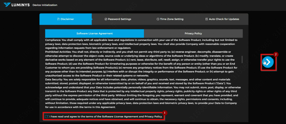
3. Review the agreement thoroughly, select "Agree," and click the right arrow to proceed to the next step. | |||
[[File:Access_Control_Initialization_3.png|1000px|link=https://wiki.luminyscorp.com/images/0/0b/Access_Control_Initialization_3.png]] | |||
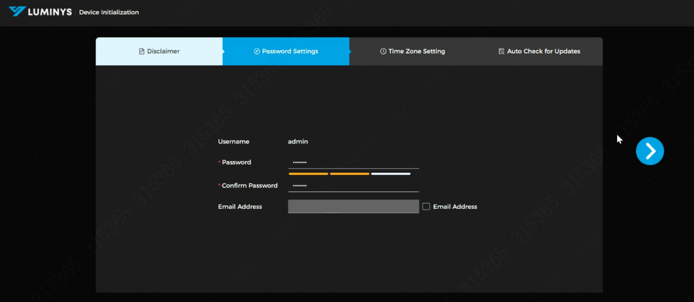
4. Set a password and provide an email address for password recovery. Click the right arrow to continue to the next step. | |||
[[File:Access_Control_Initialization_4.png|1000px|link=https://wiki.luminyscorp.com/images/1/11/Access_Control_Initialization_4.png]] | |||
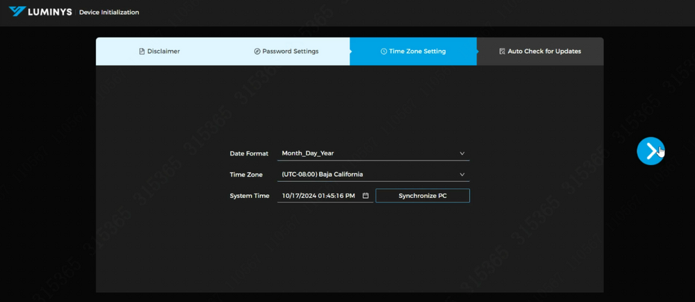
5. Select the appropriate date format and time zone, then click "Next" to proceed to the auto-update configuration. | |||
[[File:Access_Control_Initialization_5.png|1000px|link=https://wiki.luminyscorp.com/images/f/f3/Access_Control_Initialization_5.png]] | |||
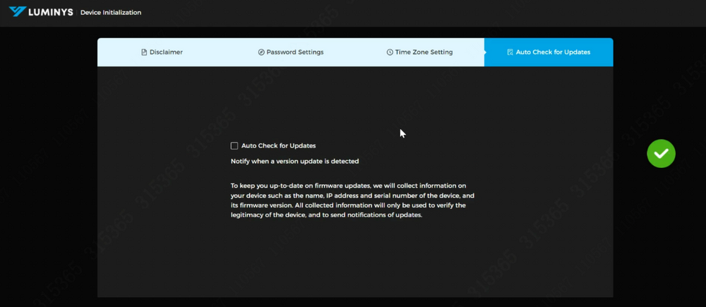
6. The auto-check for updates feature is disabled by default. It can be enabled if automatic updates for the access control system are required. | |||
[[File:Access_Control_Initialization_6.png|1000px|link=https://wiki.luminyscorp.com/images/a/ac/Access_Control_Initialization_6.png]] | |||
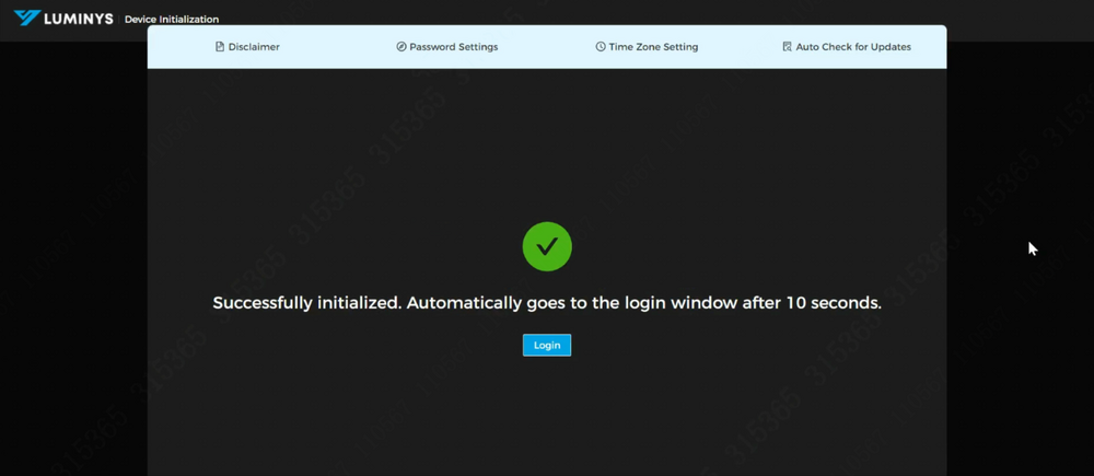
7. The device initialization is now complete. The next step involves configuring the controllers and doors for use. | |||
[[File:Access_Control_Initialization_7.png|1000px|link=https://wiki.luminyscorp.com/images/1/19/Access_Control_Initialization_7.png]] | |||
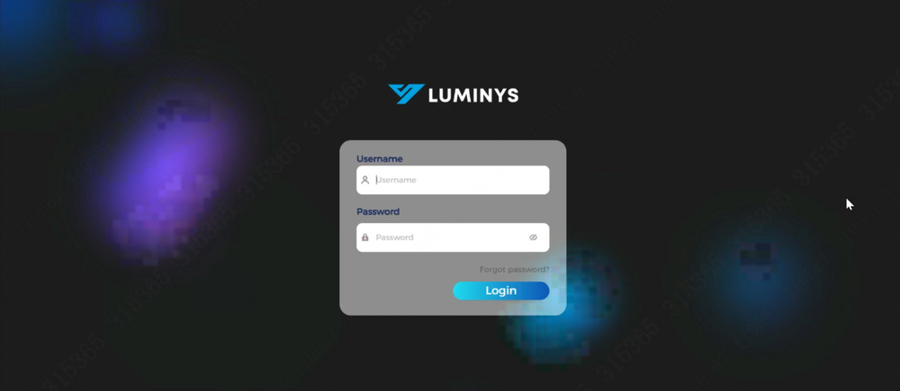
8. Log back into the access control system that was previously initialized to complete the remaining setup of the initial settings. | |||
[[File:Access_Control_Initialization_8.png|1000px|link=https://wiki.luminyscorp.com/images/7/73/Access_Control_Initialization_8.png]] | |||
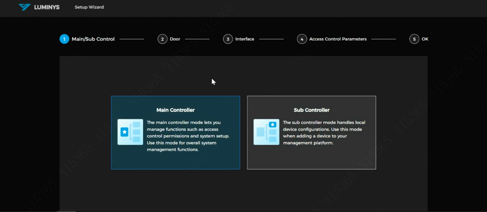
9. Upon logging into the access control system, two controller models will be presented: | |||
*Main Controller: A single main controller can manage up to 14 sub-controllers, allowing the system to consist of a total of 15 controllers and support up to 30 doors. | |||
*Sub Controller | |||
For this example, the access control will be set as the main controller, as it includes management functionality. Scroll down to view the "Next" button and proceed. | |||
[[File:Access_Control_Initialization_9.png|1000px|link=https://wiki.luminyscorp.com/images/0/02/Access_Control_Initialization_9.png]] | |||
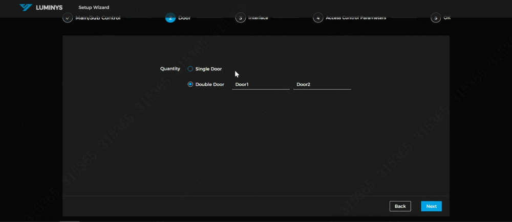
10. Select "Double Door" if both doors are to be used. If configured as a single door, it will function as a two-way door (entrance and exit). | |||
[[File:Access_Control_Initialization_10.png|1000px|link=https://wiki.luminyscorp.com/images/0/06/Access_Control_Initialization_10.png]] | |||
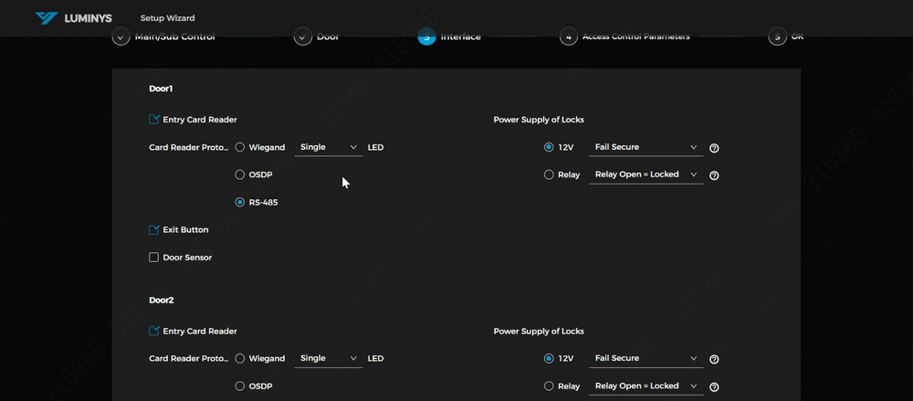
11. The following are the basic configurations for the doors. In this example, RS-485 is used. If a third-party device is being utilized, the Wiegand protocol can be selected. | |||
If door sensors or an exit button are present, the corresponding checkboxes can be selected. | |||
Additionally, attention should be given to the lock power supply, which offers two options: | |||
*Fail Secure (NO) | |||
*Fail Safe (NC) | |||
[[File:Access_Control_Initialization_11.png|1000px|link=https://wiki.luminyscorp.com/images/b/ba/Access_Control_Initialization_11.png]] | |||
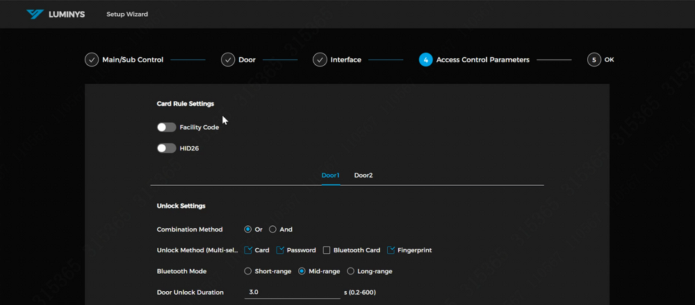
12. These are the door parameters. The controller supports HID 26-bit format. The facility code option can be enabled if the cards in use include a facility code. | |||
[[File:Access_Control_Initialization_12.png|1000px|link=https://wiki.luminyscorp.com/images/3/32/Access_Control_Initialization_12.png]] | |||
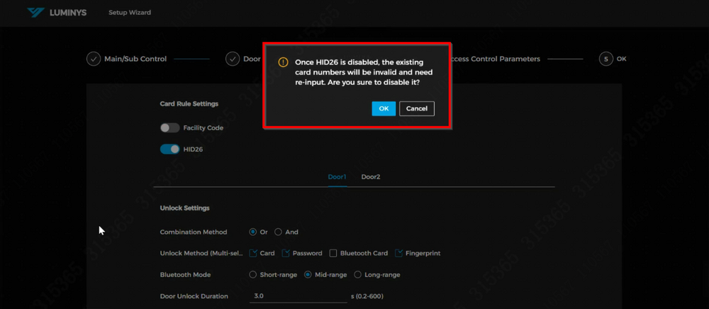
<span style=color:red;font-style:italic;font-weight:bold>Note: Once HID 26-bit is enabled, disabling it later will invalidate the existing card numbers, requiring them to be re-entered.</span> | |||
[[File:Access_Control_Initialization_13.png|1000px|link=https://wiki.luminyscorp.com/images/6/67/Access_Control_Initialization_13.png]] | |||
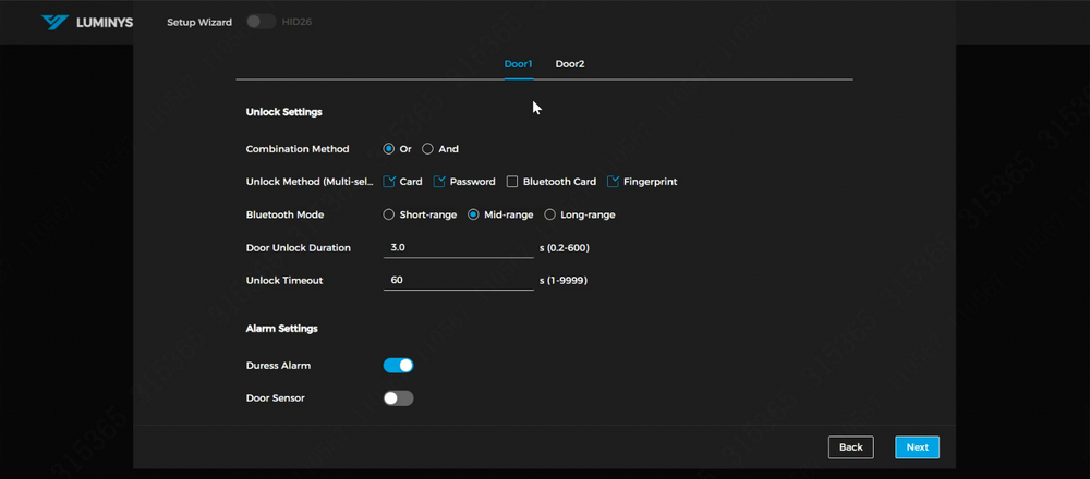
The available unlock methods for the doors are displayed. In this example, the "Or" unlocking method will be used, with cards and passwords selected as the unlock options. For the Bluetooth unlock option, you can choose between "Short-range," "Mid-range," or "Long-range" modes. | |||
To enable a Duress Alarm, activate the slider next to Duress Alarm, allowing the door to trigger alarms when a duress card is used. | |||
To enable alarms via a door sensor, activate the slider next to Door Detector. | |||
[[File:Access_Control_Initialization_14.png|1000px|link=https://wiki.luminyscorp.com/images/d/d6/Access_Control_Initialization_14.png]] | |||
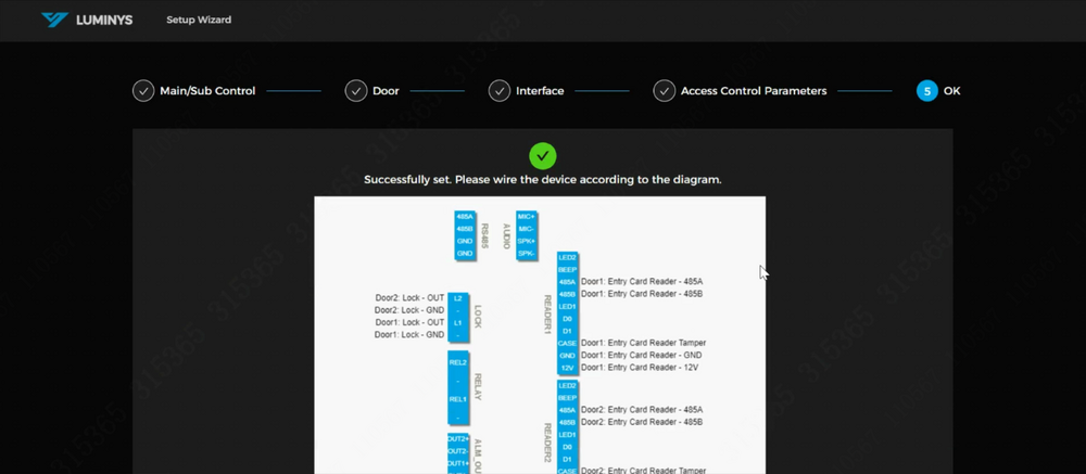
13. The wiring diagram for the controller is available for download. The "Apply" and "Download Image" buttons are located below the diagram; scrolling down may be required to view them. | |||
[[File:Access_Control_Initialization_15.png|1000px|link=https://wiki.luminyscorp.com/images/4/43/Access_Control_Initialization_15.png]] | |||
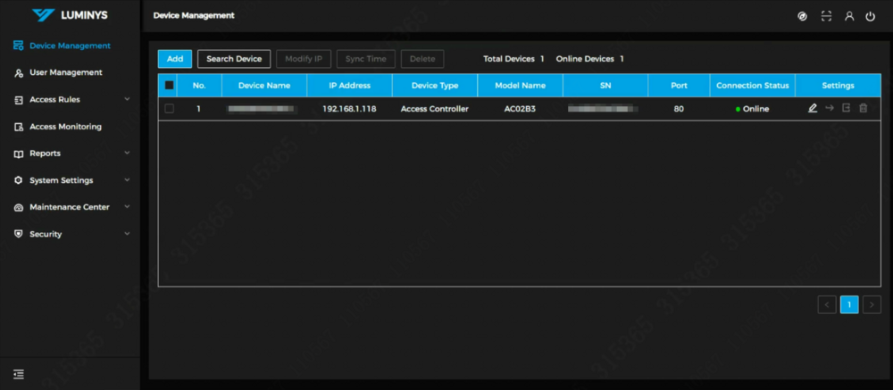
14. This is the main page of the web controller. | |||
[[File:Access_Control_Initialization_16.png|1000px|link=https://wiki.luminyscorp.com/images/c/c6/Access_Control_Initialization_16.png]] | |||
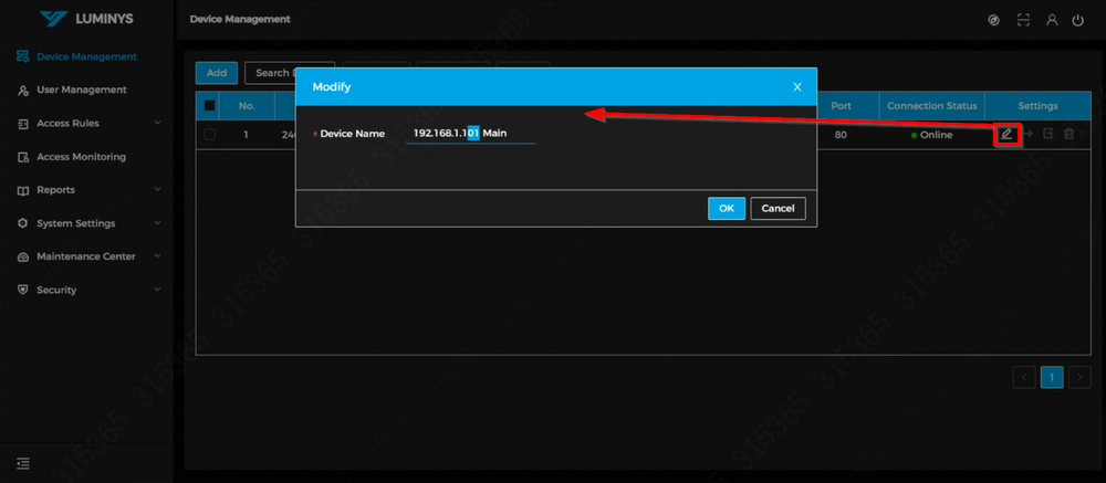
15. It is recommended to modify the name if multiple controllers are used in the same environment for easier identification. | |||
[[File:Access_Control_Initialization_17.png|1000px|link=https://wiki.luminyscorp.com/images/3/32/Access_Control_Initialization_17.png]] | |||
16. This concludes the initialization process of the access control system. | |||
Latest revision as of 09:58, 15 November 2024
Access Control Initialization and Basic Setup
Description
This tutorial will go over how to initialize access control and some basic setup.
Prerequisites
- Access control powered and connected on local network.
Video Instructions
Coming soon
Step by Step Instructions
1. Open a web browser and input the IP address of the access control system into the address bar. Press Enter to access the system's web GUI.
2. The LumiUtility software can also be used to initialize the access control system. Both methods offer efficient options for system setup and management, allowing flexibility based on specific requirements.
3. Review the agreement thoroughly, select "Agree," and click the right arrow to proceed to the next step.
4. Set a password and provide an email address for password recovery. Click the right arrow to continue to the next step.
5. Select the appropriate date format and time zone, then click "Next" to proceed to the auto-update configuration.
6. The auto-check for updates feature is disabled by default. It can be enabled if automatic updates for the access control system are required.
7. The device initialization is now complete. The next step involves configuring the controllers and doors for use.
8. Log back into the access control system that was previously initialized to complete the remaining setup of the initial settings.
9. Upon logging into the access control system, two controller models will be presented:
- Main Controller: A single main controller can manage up to 14 sub-controllers, allowing the system to consist of a total of 15 controllers and support up to 30 doors.
- Sub Controller
For this example, the access control will be set as the main controller, as it includes management functionality. Scroll down to view the "Next" button and proceed.
10. Select "Double Door" if both doors are to be used. If configured as a single door, it will function as a two-way door (entrance and exit).
11. The following are the basic configurations for the doors. In this example, RS-485 is used. If a third-party device is being utilized, the Wiegand protocol can be selected.
If door sensors or an exit button are present, the corresponding checkboxes can be selected. Additionally, attention should be given to the lock power supply, which offers two options:
- Fail Secure (NO)
- Fail Safe (NC)
12. These are the door parameters. The controller supports HID 26-bit format. The facility code option can be enabled if the cards in use include a facility code.
Note: Once HID 26-bit is enabled, disabling it later will invalidate the existing card numbers, requiring them to be re-entered.
The available unlock methods for the doors are displayed. In this example, the "Or" unlocking method will be used, with cards and passwords selected as the unlock options. For the Bluetooth unlock option, you can choose between "Short-range," "Mid-range," or "Long-range" modes.
To enable a Duress Alarm, activate the slider next to Duress Alarm, allowing the door to trigger alarms when a duress card is used.
To enable alarms via a door sensor, activate the slider next to Door Detector.
13. The wiring diagram for the controller is available for download. The "Apply" and "Download Image" buttons are located below the diagram; scrolling down may be required to view them.
14. This is the main page of the web controller.
15. It is recommended to modify the name if multiple controllers are used in the same environment for easier identification.
16. This concludes the initialization process of the access control system.

