Video doorbell/Installation Instruction: Difference between revisions
Techsupport (talk | contribs) |
Techsupport (talk | contribs) |
||
| (One intermediate revision by the same user not shown) | |||
| Line 8: | Line 8: | ||
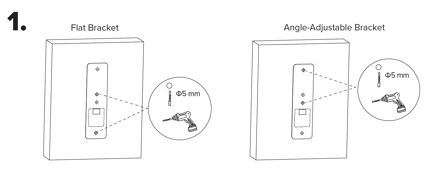
1. Remove any existing doorbell system(s). Position and level the mounting template on the wall and drill 5 mm holes at the marked points for your selected bracket. | 1. Remove any existing doorbell system(s). Position and level the mounting template on the wall and drill 5 mm holes at the marked points for your selected bracket. | ||
[[File:Vdb_installation_1.png| | [[File:Vdb_installation_1.png|1080px|link=https://wiki.luminyscorp.com/images/3/3e/Vdb_installation_1.png]] | ||
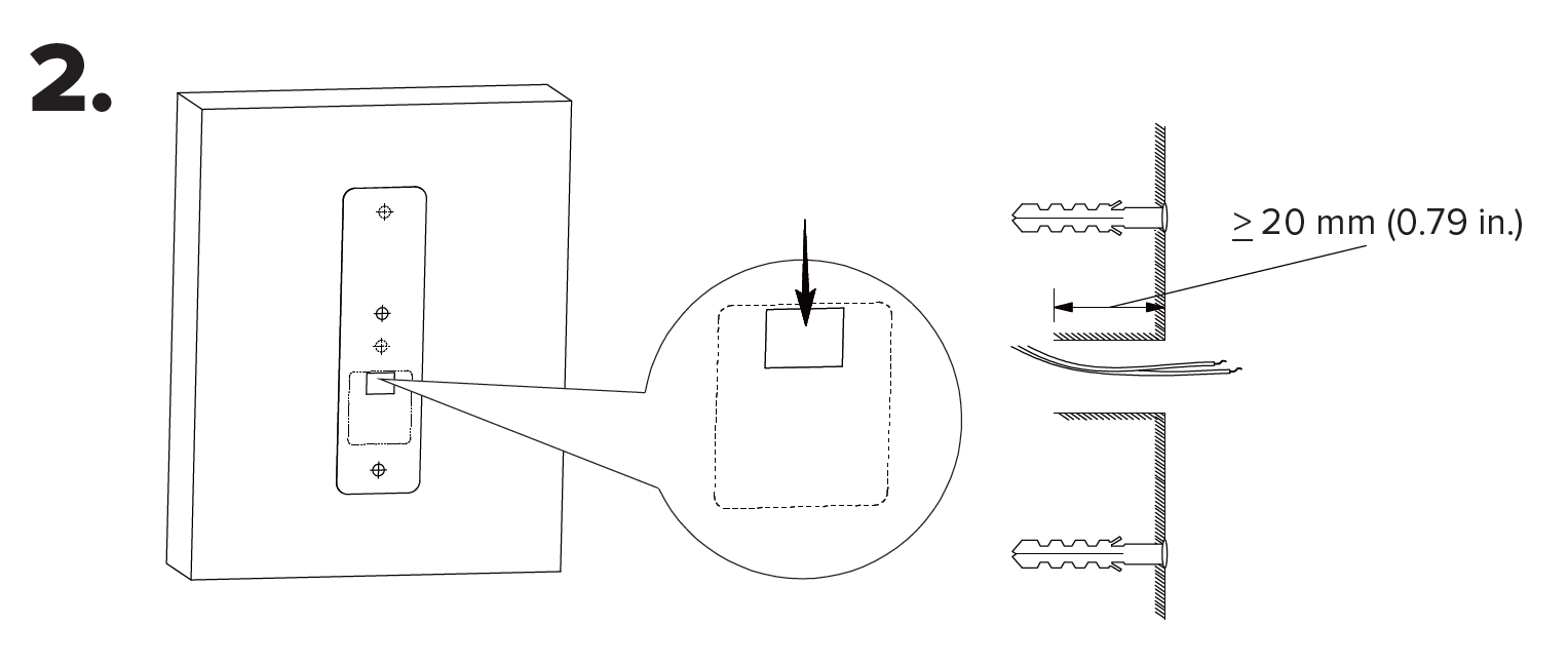
2. Use the mounting template to drill a ≥20 mm wiring hole, then tap the wall anchors into the holes until flush. If using the flat bracket, proceed to Step 3. If using the angle-adjustable bracket, go to Step 4. | |||
[[File:Vdb_installation_2.png|1080px|link=https://wiki.luminyscorp.com/images/e/e2/Vdb_installation_2.png]] | |||
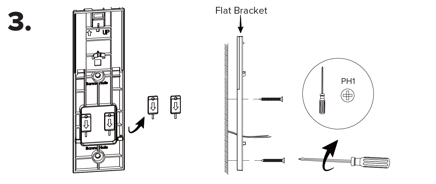
3. For flat bracket installations, remove and retain the two locking tabs. Align the flat bracket with the wall anchors. Secure the bracket with the supplied flat-head Phillips head screws. | |||
[[File:Vdb_installation_3.png|1080px|link=https://wiki.luminyscorp.com/images/8/8f/Vdb_installation_3.png]] | |||
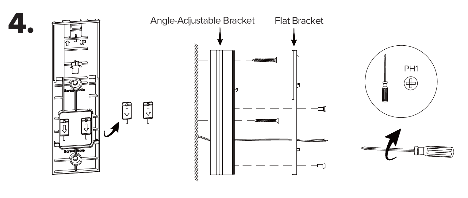
4. For angle-adjustable bracket installations, remove and retain the two locking tabs. Align the angle-adjustable bracket with the wall anchors and secure it using the supplied flat-head Phillips screws. Align the flat bracket on top and fasten it with the supplied round-head Phillips screws. | |||
[[File:Vdb_installation_4.png|1080px|link=https://wiki.luminyscorp.com/images/9/9c/Vdb_installation_4.png]] | |||
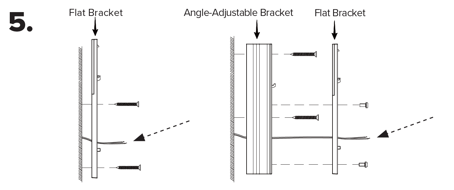
5. Check the power-supply wire length. If sufficient, proceed to Step 6 and skip step 7. If too short, proceed immediately to Step 7. | |||
[[File:Vdb_installation_5.png|1080px|link=https://wiki.luminyscorp.com/images/e/e9/Vdb_installation_5.png]] | |||
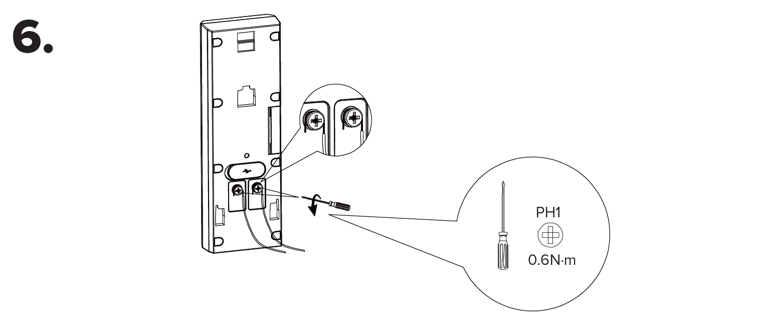
6. If the power supply wires are of sufficient length, connect them to the doorbell terminals and tighten the terminal screws. | |||
[[File:Vdb_installation_6.png|1080px|link=https://wiki.luminyscorp.com/images/5/51/Vdb_installation_6.png]] | |||
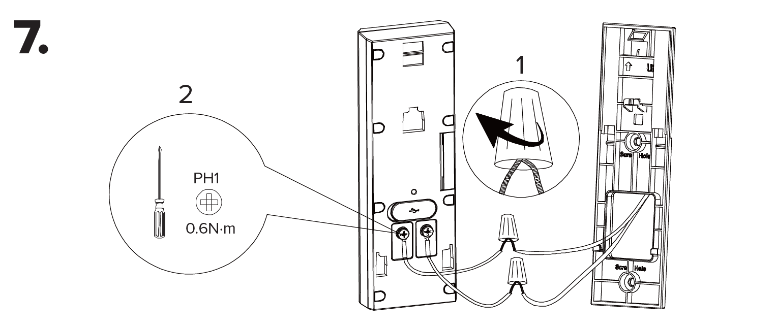
7. If the power supply wires are too short, add the supplied extension using the wire nuts. Connect the extended wires to the doorbell terminals and tighten the terminal screws. | |||
[[File:Vdb_installation_7.png|1080px|link=https://wiki.luminyscorp.com/images/c/c2/Vdb_installation_7.png]] | |||
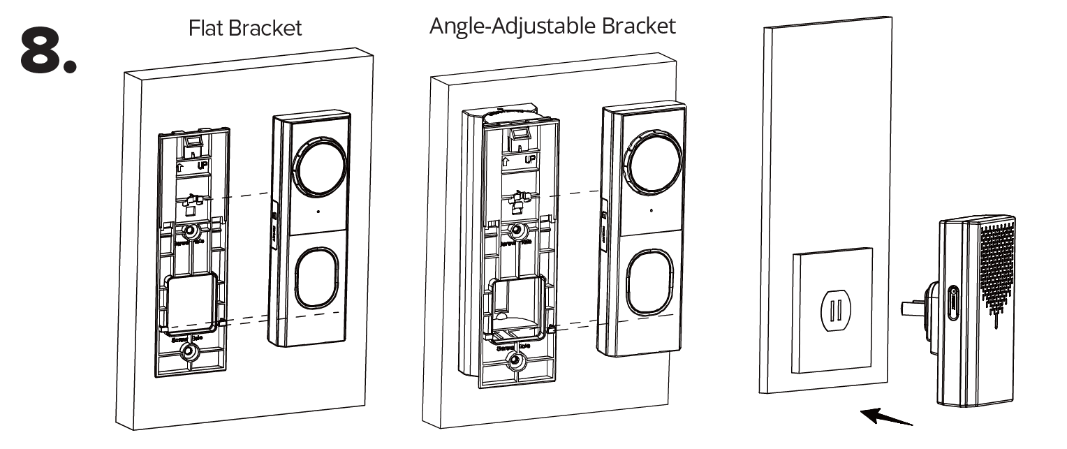
8. Slide the doorbell onto the bracket. Turn the circuit breaker back on. Plug the wireless chime into a wall outlet. | |||
[[File:Vdb_installation_8.png|1080px|link=https://wiki.luminyscorp.com/images/5/53/Vdb_installation_8.png]] | |||
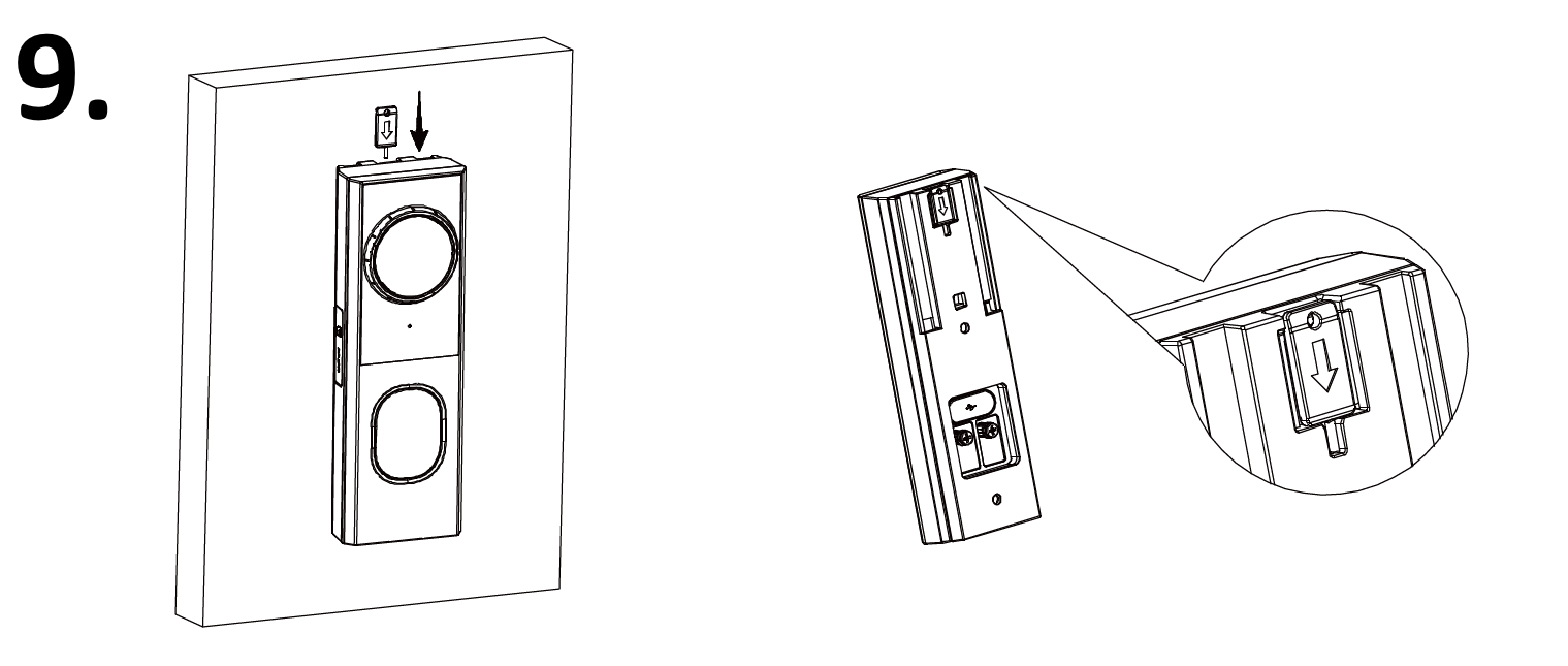
9. Insert the locking tab into the gap between the flat bracket and the wall (or angle-adjustable bracket). | |||
[[File:Vdb_installation_9.png|1080px|link=https://wiki.luminyscorp.com/images/3/31/Vdb_installation_9.png]] | |||
Latest revision as of 15:21, 13 May 2026

Description
This tutorial will go over on how to physically setup the video doorbell.
Step by Step Instructions
1. Remove any existing doorbell system(s). Position and level the mounting template on the wall and drill 5 mm holes at the marked points for your selected bracket.
2. Use the mounting template to drill a ≥20 mm wiring hole, then tap the wall anchors into the holes until flush. If using the flat bracket, proceed to Step 3. If using the angle-adjustable bracket, go to Step 4.
3. For flat bracket installations, remove and retain the two locking tabs. Align the flat bracket with the wall anchors. Secure the bracket with the supplied flat-head Phillips head screws.
4. For angle-adjustable bracket installations, remove and retain the two locking tabs. Align the angle-adjustable bracket with the wall anchors and secure it using the supplied flat-head Phillips screws. Align the flat bracket on top and fasten it with the supplied round-head Phillips screws.
5. Check the power-supply wire length. If sufficient, proceed to Step 6 and skip step 7. If too short, proceed immediately to Step 7.
6. If the power supply wires are of sufficient length, connect them to the doorbell terminals and tighten the terminal screws.
7. If the power supply wires are too short, add the supplied extension using the wire nuts. Connect the extended wires to the doorbell terminals and tighten the terminal screws.
8. Slide the doorbell onto the bracket. Turn the circuit breaker back on. Plug the wireless chime into a wall outlet.
9. Insert the locking tab into the gap between the flat bracket and the wall (or angle-adjustable bracket).