LumiWatch/LumiWatch installation procedure: Difference between revisions
Techsupport (talk | contribs) |
Techsupport (talk | contribs) |
||
| (63 intermediate revisions by the same user not shown) | |||
| Line 6: | Line 6: | ||
This tutorial will go over how to do physical installation for LumiWatch. </br> | This tutorial will go over how to do physical installation for LumiWatch. </br> | ||
<span style = "color: Red"> '''Note:''' This guide is intended to be used in conjunction with the included printed installation guide. It is not intended to replace the installation guide. Please refer to both guides during the installation process. </span> | <span style = "color: Red"> '''Note:''' This guide is intended to be used in conjunction with the included printed installation guide. It is not intended to replace the installation guide. Please refer to both guides during the installation process. </span> | ||
===Prerequisite=== | |||
1. Phillips screwdriver </br> | |||
2. 4G SIM card | |||
===Step by Step Instructions=== | ===Step by Step Instructions=== | ||
| Line 20: | Line 24: | ||
| | ||
c. Insert your SIM card. | c. Insert your SIM card to the SIM holder.</br> | ||
| |||
[[File:LumiWatch_installation_1c.jpg|512px|link=https://wiki.luminyscorp.com/images/c/cb/LumiWatch_installation_1c.jpg]] | |||
| | ||
[[File:LumiWatch_installation_1d.jpg|512px|link=https://wiki.luminyscorp.com/images/5/5b/LumiWatch_installation_1d.jpg]] | |||
[[File:LumiWatch_installation_1d.jpg| | |||
| | ||
d. Reinsert the holder into the router, and reinstall the cap. | d. Reinsert the holder into the router, and reinstall the cap.</br> | ||
| |||
[[File:LumiWatch_installation_1e.jpg|512px|link=https://wiki.luminyscorp.com/images/a/a4/LumiWatch_installation_1e.jpg]] | |||
| |||
[[File:LumiWatch_installation_1f.jpg|512px|link=https://wiki.luminyscorp.com/images/e/ed/LumiWatch_installation_1f.jpg]] | |||
2. Mount the bracket — | 2. Mount the bracket — The pole installation is shown as an example. </br> | ||
| |||
Secure the pole mounting bracket to the pole with the five metal clamps. Use a Phillips screwdriver (not included). | |||
| |||
[[File:LumiWatch_installation_2.jpg|512px|link=https://wiki.luminyscorp.com/images/d/da/LumiWatch_installation_2.jpg]] | |||
3. Hang the battery box — Hang the battery box onto the pole bracket. The snap-fit holds it in place while you secure the screws. Use the 5 mm hex wrench to tighten the ten M6×16 screws. | 3. Hang the battery box — Hang the battery box onto the pole bracket. The snap-fit holds it in place while you secure the screws. Use the 5 mm hex wrench to tighten the ten M6×16 screws.</br> | ||
| |||
[[File:LumiWatch_installation_3.jpg|512px|link=https://wiki.luminyscorp.com/images/8/86/LumiWatch_installation_3.jpg]] | |||
4. Install the PV angle bracket — Install the PV angle bracket on the battery box. Adjust the bracket to between 10° and 75° based on your latitude. Use the 5 mm hex wrench to tighten the six M6×16 screws. | 4. Install the PV (Photovoltaic) angle bracket — Install the PV angle bracket on the battery box. Adjust the bracket to between 10° and 75° based on your latitude. Use the 5 mm hex wrench to tighten the six M6×16 screws. | ||
| |||
[[File:LumiWatch_installation_4a.jpg|512px|link=https://wiki.luminyscorp.com/images/9/9b/LumiWatch_installation_4a.jpg]] | |||
[[File:LumiWatch_installation_4b.jpg|512px|link=https://wiki.luminyscorp.com/images/d/d4/LumiWatch_installation_4b.jpg]] | |||
5. Hang the PV module — Attach the safety cable to the PV module. Hang the module onto the PV angle bracket — the snap-fit holds it in place. Use the 5 mm hex wrench to tighten the four M6×16 screws. | 5. Hang the PV module — Attach the safety cable to the PV module. Hang the module onto the PV angle bracket — the snap-fit holds it in place. Use the 5 mm hex wrench to tighten the four M6×16 screws. | ||
| |||
[[File:LumiWatch_installation_5a.jpg|512px|link=https://wiki.luminyscorp.com/images/a/ac/LumiWatch_installation_5a.jpg]] | |||
| |||
[[File:LumiWatch_installation_5b.jpg|512px|link=https://wiki.luminyscorp.com/images/9/9a/LumiWatch_installation_5b.jpg]] | |||
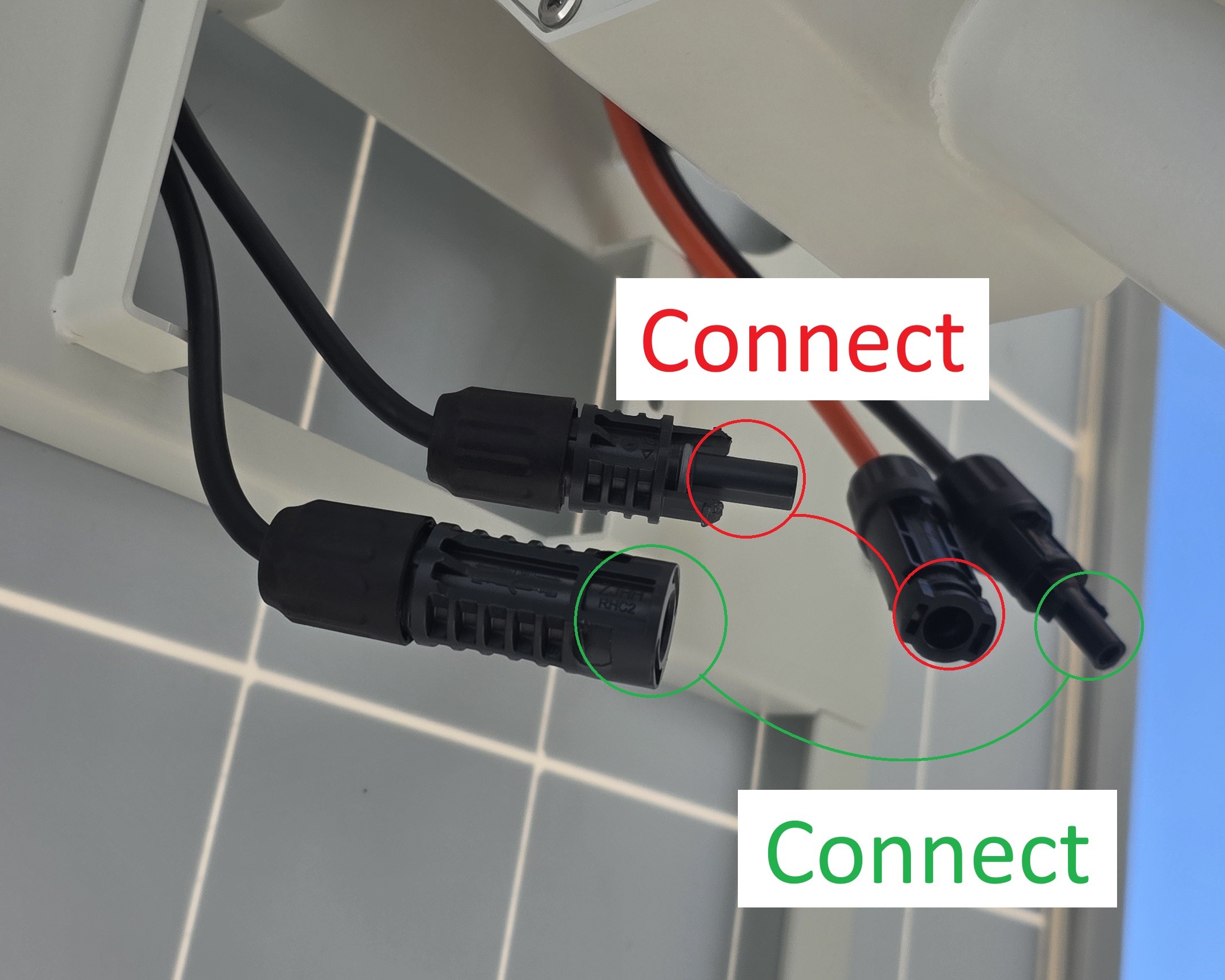
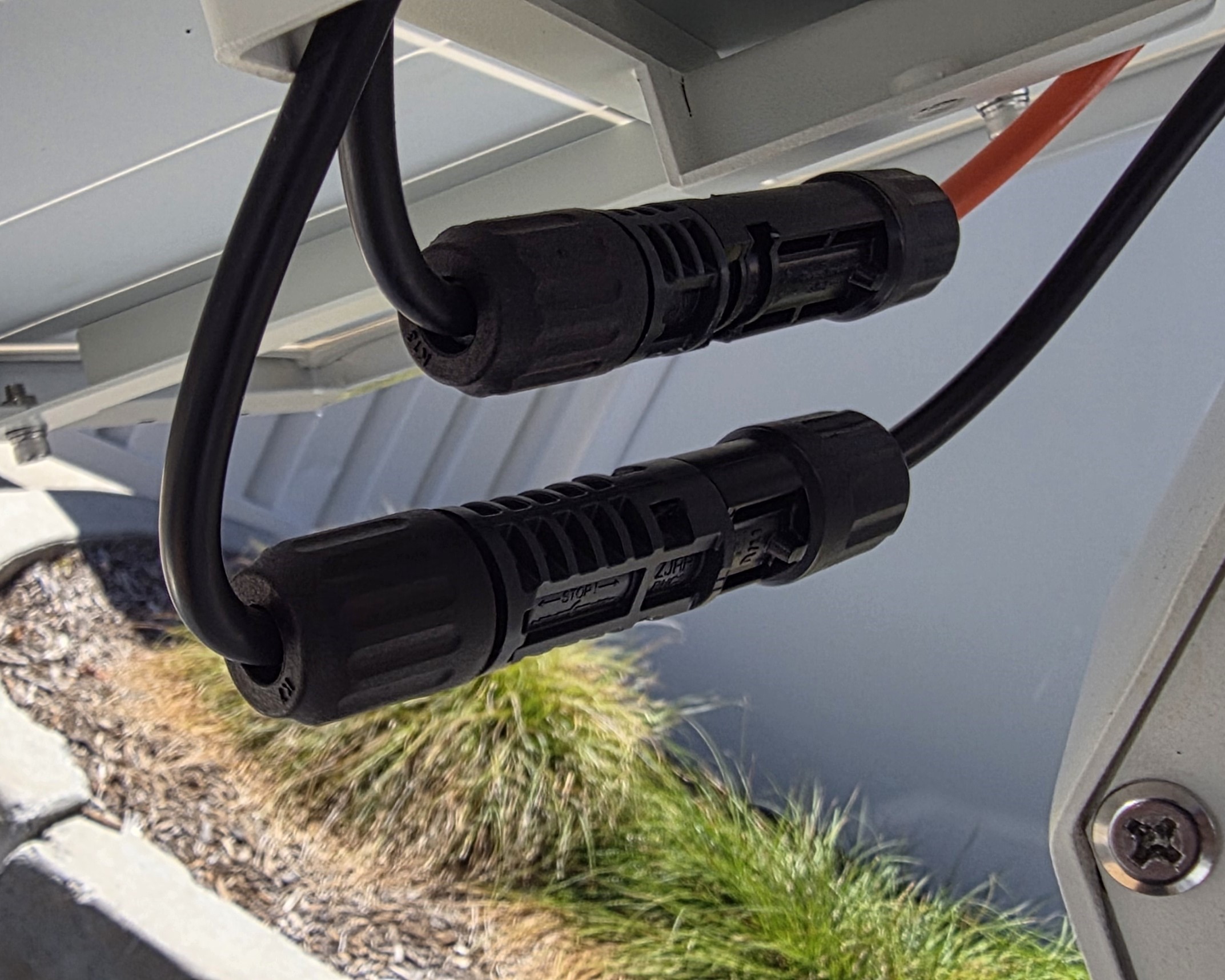
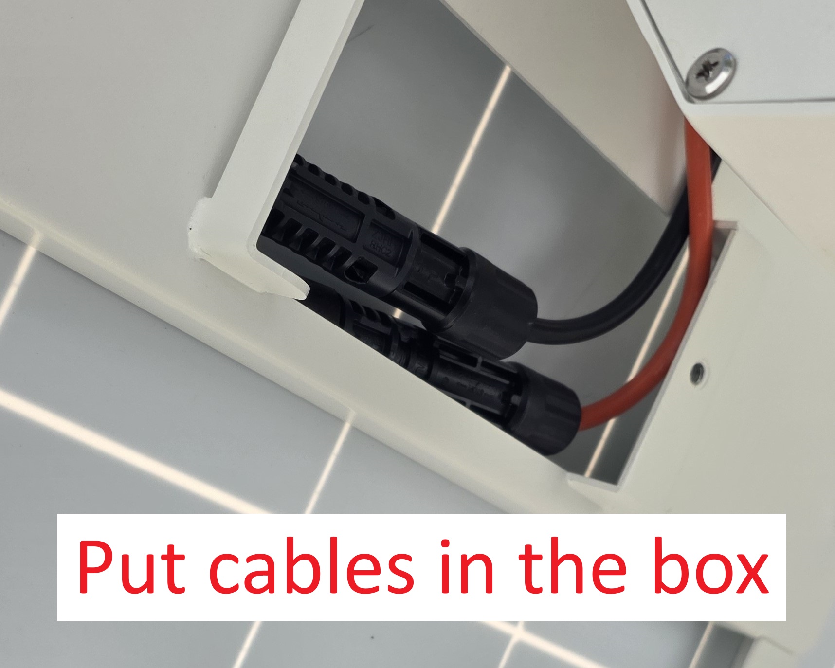
6. Connect the PV wiring — Mate the two sets of MC4 connectors on the PV wiring harness. Place the connectors inside the cable junction box and close the cable cover. Use the 5 mm hex wrench to tighten the M6×16 screw. | 6. Connect the PV wiring — Mate the two sets of MC4 connectors on the PV wiring harness. Place the connectors inside the cable junction box and close the cable cover. Use the 5 mm hex wrench to tighten the M6×16 screw. | ||
| |||
[[File:LumiWatch_installation_6a.jpg|512px|link=https://wiki.luminyscorp.com/images/d/d5/LumiWatch_installation_6a.jpg]] | |||
| |||
[[File:LumiWatch_installation_6b.jpg|512px|link=https://wiki.luminyscorp.com/images/2/2f/LumiWatch_installation_6b.jpg]] </br> | |||
| |||
[[File:LumiWatch_installation_6c.jpg|512px|link=https://wiki.luminyscorp.com/images/1/1f/LumiWatch_installation_6c.jpg]] | |||
| |||
[[File:LumiWatch_installation_6d.jpg|512px|link=https://wiki.luminyscorp.com/images/1/13/LumiWatch_installation_6d.jpg]] | |||
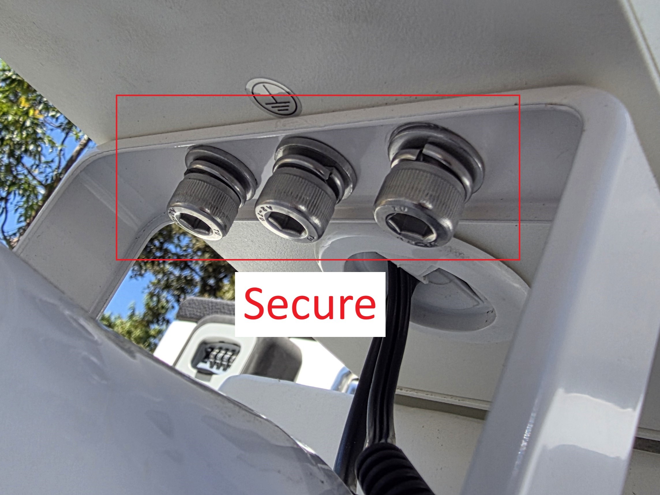
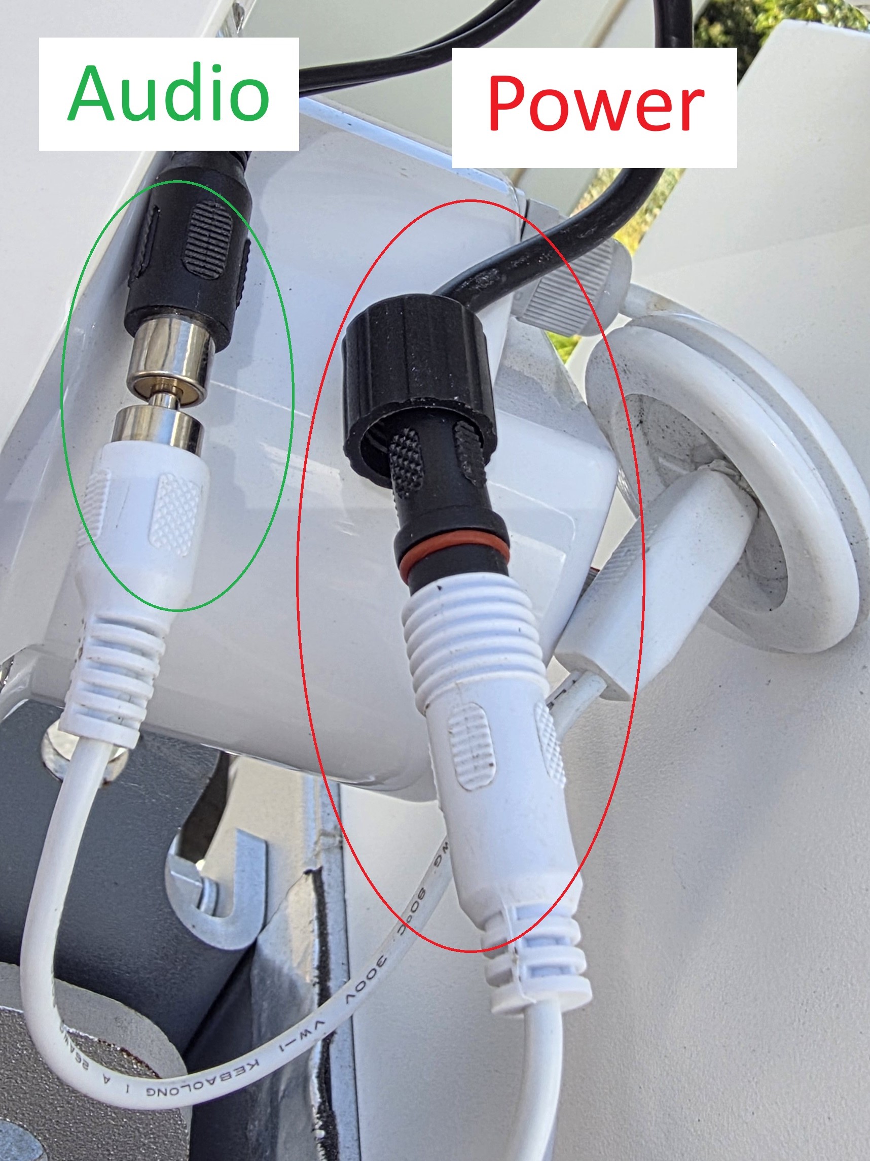
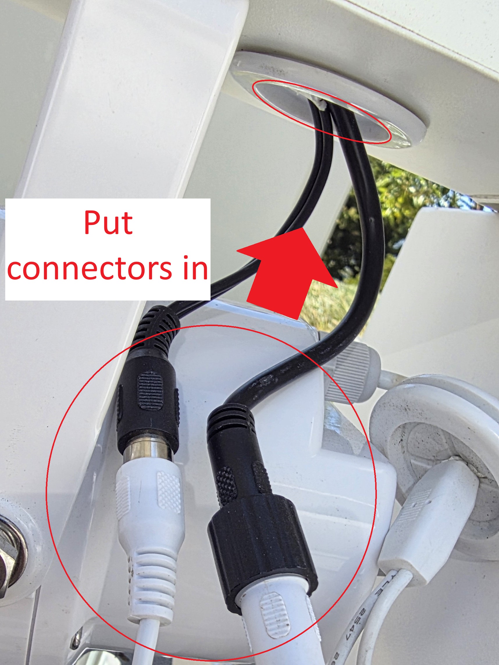
7. Install the speaker — Use the 6 mm hex wrench and three M8×18 screws to secure the speaker to the bottom of the battery box. Connect the speaker's audio and power cables. Tuck the harness connector into the hole at the bottom of the box. | 7. Install the speaker — Use the 6 mm hex wrench and three M8×18 screws to secure the speaker to the bottom of the battery box. Connect the speaker's audio and power cables. Tuck the harness connector into the hole at the bottom of the box. | ||
8. Mount the camera — Remove the plastic plugs or screws from the bolt holes on the camera mounting bracket. Mount the camera onto the bracket using the fasteners | | ||
[[File:LumiWatch_installation_7a.jpg|512px|link=https://wiki.luminyscorp.com/images/8/87/LumiWatch_installation_7a.jpg]]</br> | |||
| |||
[[File:LumiWatch_installation_7b.jpg|512px|link=https://wiki.luminyscorp.com/images/f/f4/LumiWatch_installation_7b.jpg]] | |||
| |||
[[File:LumiWatch_installation_7c.jpg|512px|link=https://wiki.luminyscorp.com/images/2/27/LumiWatch_installation_7c.jpg]] | |||
| |||
[[File:LumiWatch_installation_7d.jpg|512px|link=https://wiki.luminyscorp.com/images/a/a7/LumiWatch_installation_7d.jpg]] | |||
8. Mount the camera — Remove the plastic plugs or screws from the bolt holes on the camera mounting bracket. Mount the camera onto the bracket using the fasteners. | |||
| |||
[[File:LumiWatch_installation_8a.jpg|512px|link=https://wiki.luminyscorp.com/images/b/ba/LumiWatch_installation_8a.jpg]] | |||
| |||
[[File:LumiWatch_installation_8b.jpg|512px|link=https://wiki.luminyscorp.com/images/7/74/LumiWatch_installation_8b.jpg]]</br> | |||
| |||
[[File:LumiWatch_installation_8c.jpg|512px|link=https://wiki.luminyscorp.com/images/b/ba/LumiWatch_installation_8c.jpg]] | |||
9. Hang the camera assembly — Hang the camera assembly under the round mounting tube of the battery box. The snap-fit holds it in place. Use the 5 mm hex wrench to tighten the four M6×16 screws. | 9. Hang the camera assembly — Hang the camera assembly under the round mounting tube of the battery box. The snap-fit holds it in place. Use the 5 mm hex wrench to tighten the four M6×16 screws. | ||
| |||
[[File:LumiWatch_installation_9ab.gif|512px|link=https://wiki.luminyscorp.com/images/a/ab/LumiWatch_installation_9ab.gif]]</br> | |||
| |||
[[File:LumiWatch_installation_9c.jpg|512px|link=https://wiki.luminyscorp.com/images/d/d7/LumiWatch_installation_9c.jpg]] | |||
10. Connect the camera cables — Connect the camera's power cable, Ethernet cable, and audio cable. Close the rear cover of the camera mounting bracket. Use the 5 mm hex wrench to tighten the three M6×16 screws. | 10. Connect the camera cables — Connect the camera's power cable, Ethernet cable, and audio cable. Close the rear cover of the camera mounting bracket. Use the 5 mm hex wrench to tighten the three M6×16 screws. | ||
| |||
[[File:LumiWatch_installation_10a.jpg|512px|link=https://wiki.luminyscorp.com/images/2/28/LumiWatch_installation_10a.jpg]] | |||
| |||
[[File:LumiWatch_installation_10b.jpg|512px|link=https://wiki.luminyscorp.com/images/e/e1/LumiWatch_installation_10b.jpg]]</br> | |||
| |||
[[File:LumiWatch_installation_10c.jpg|512px|link=https://wiki.luminyscorp.com/images/d/d7/LumiWatch_installation_10c.jpg]] | |||
11. Install the antenna — Install the four antennas onto the antenna mount. Match each antenna to its port: two 4G antennas and two Wi-Fi antennas. | 11. Install the antenna — Install the four antennas onto the antenna mount. Match each antenna to its port: two 4G antennas and two Wi-Fi antennas. | ||
| |||
[[File:LumiWatch_installation_11.jpg|1024px|link=https://wiki.luminyscorp.com/images/b/bf/LumiWatch_installation_11.jpg]] | |||
12. Press the battery switch | |||
| |||
[[File:LumiWatch_installation_12a.jpg|512px|link=https://wiki.luminyscorp.com/images/1/11/LumiWatch_installation_12a.jpg]] | |||
[[File:LumiWatch_installation_12b.jpg|512px|link=https://wiki.luminyscorp.com/images/4/44/LumiWatch_installation_12b.jpg]] | |||
13. Check the battery indicator light against the status table below. If the indicator does not match any listed pattern, contact technical support. | |||
{| style="border: none;" | |||
| style="vertical-align: top; border: none; padding-right: 15px;" | | |||
| |||
[[File:LumiWatch_installation_13.jpg|308px|link=https://wiki.luminyscorp.com/images/c/c6/LumiWatch_installation_13.jpg]] | |||
| style="vertical-align: top; border: none;" | | |||
{| class="wikitable" style="width:690px;" | |||
! Load connected !! Battery state !! Indicator | |||
|- | |||
| Yes || Fully charged || Steady on | |||
|- | |||
| Yes || Not fully charged, not charging || Off 2 s, then two fast blinks (0.2 s) | |||
|- | |||
| Yes || Not fully charged, charging || Continuous fast blink (0.2 s) | |||
|- | |||
| No || Low battery, not charging || Steady off | |||
|- | |||
| No || Low battery, charging || Continuous blink (1 s) | |||
|- | |||
| No || Fault – overvoltage, overcurrent, or battery not connected || Off 5 s, then one blink (1 s) | |||
|} | |||
|} | |||
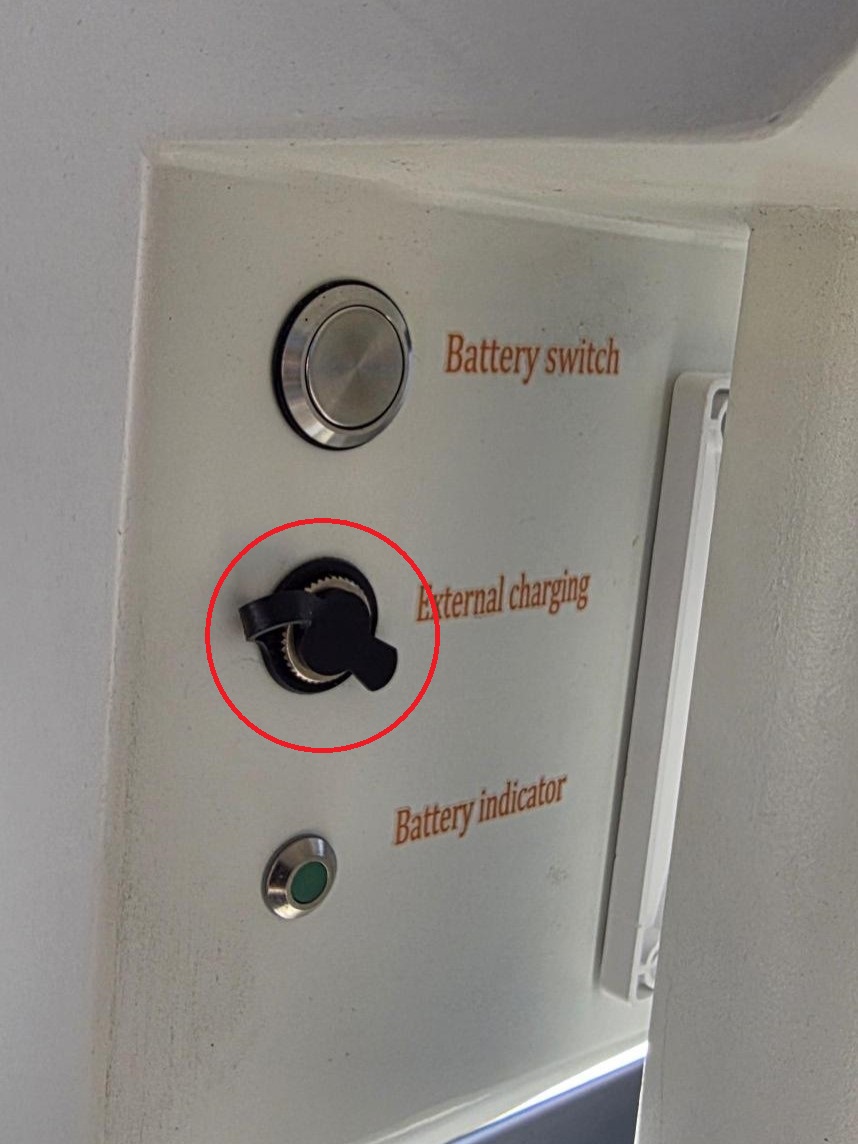
14. You can power the unit from a wall outlet through the external charging port using an AC-DC adapter. Do not use an AC-output adapter — the unit requires DC. The plug must measure 5.5 mm outer diameter / 2.5 mm inner diameter, center positive. Use a 24 VDC / 5 A adapter. | |||
| |||
[[File:LumiWatch_installation_14.jpg|512px|link=https://wiki.luminyscorp.com/images/c/c1/LumiWatch_installation_14.jpg]] | |||
Latest revision as of 11:08, 4 August 2026

LumiWatch installation procedure
Description
This tutorial will go over how to do physical installation for LumiWatch.
Note: This guide is intended to be used in conjunction with the included printed installation guide. It is not intended to replace the installation guide. Please refer to both guides during the installation process.
Prerequisite
1. Phillips screwdriver
2. 4G SIM card
Step by Step Instructions
1. Install the SIM card:
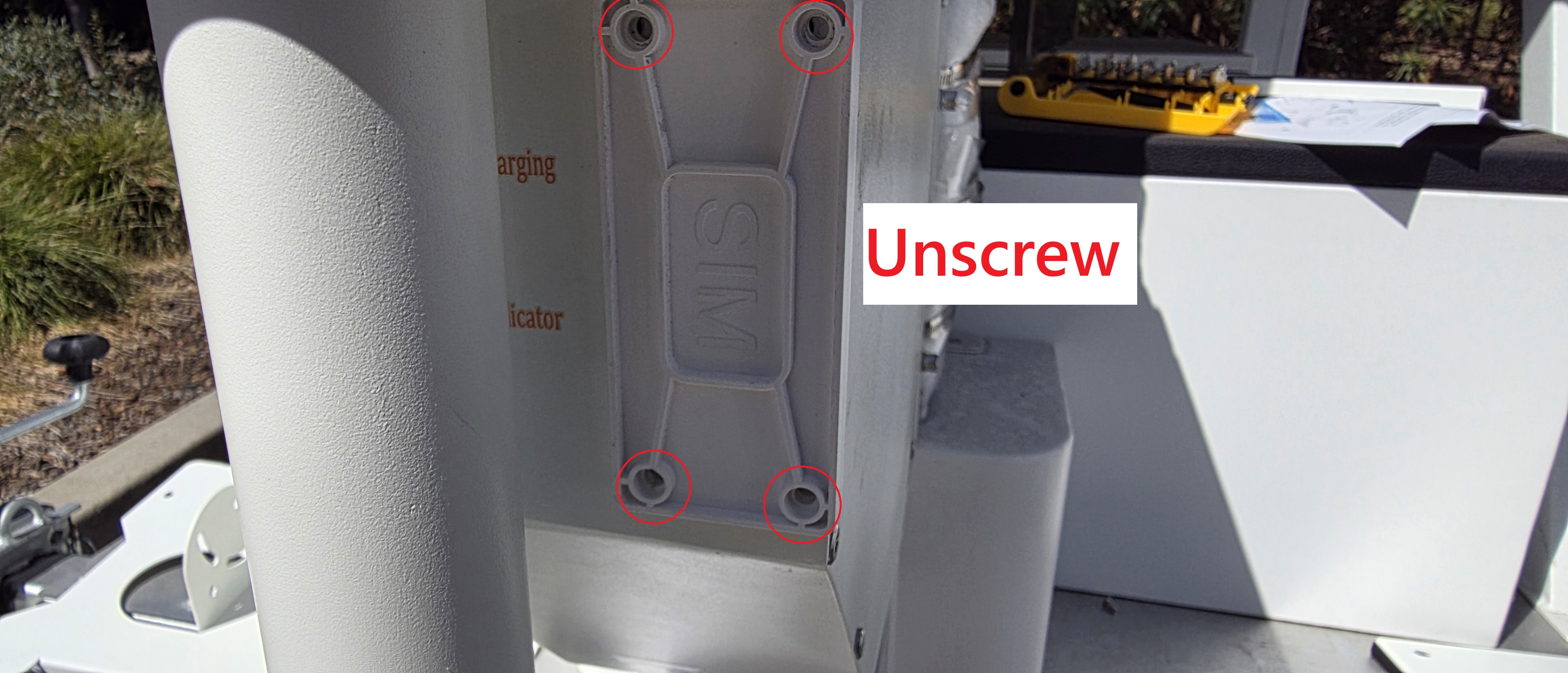
a. Use the 2.5 mm hex wrench to unscrew the SIM card cap.
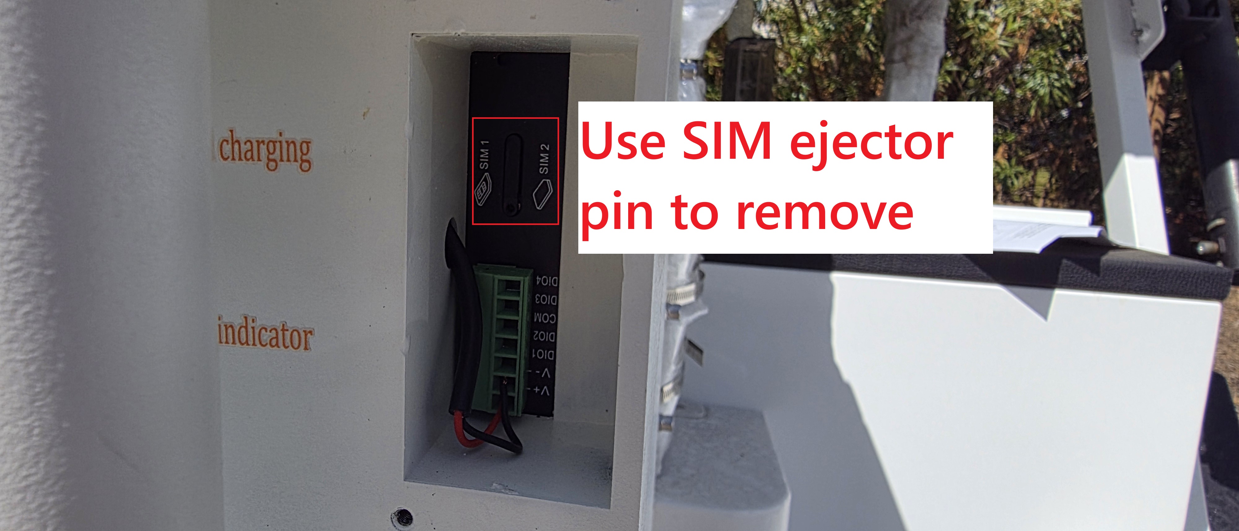
b. Use the SIM ejector pin to remove the SIM holder from the router.
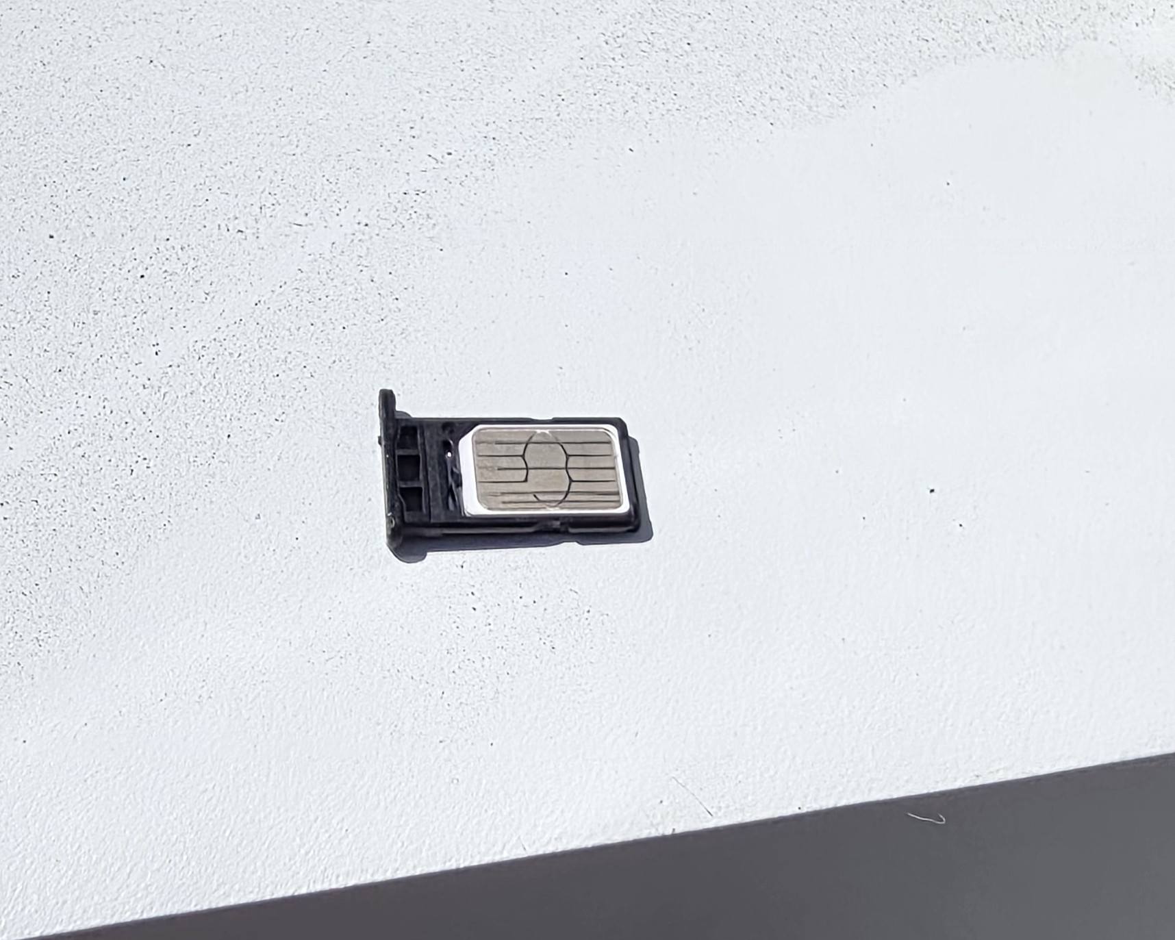
c. Insert your SIM card to the SIM holder.
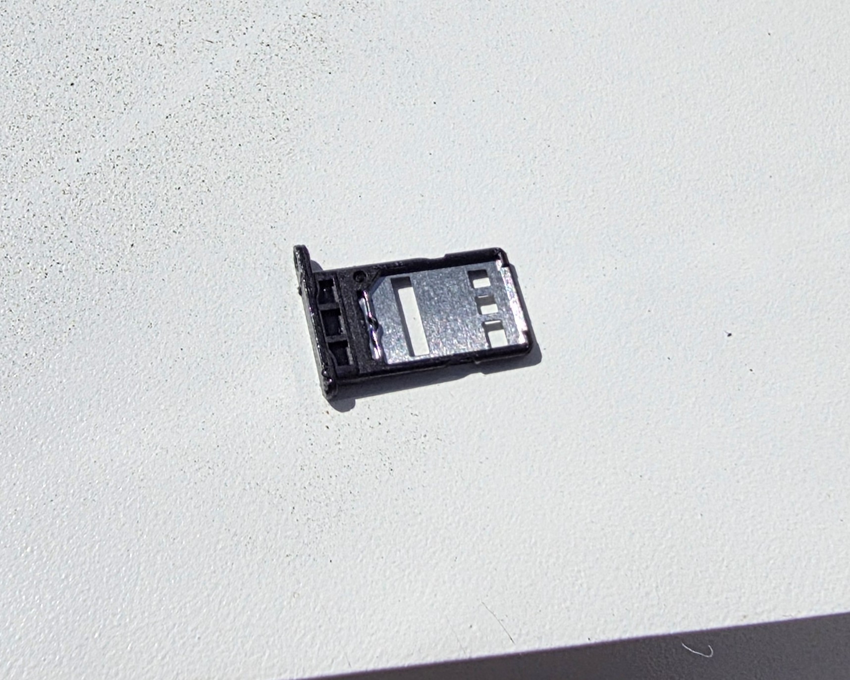
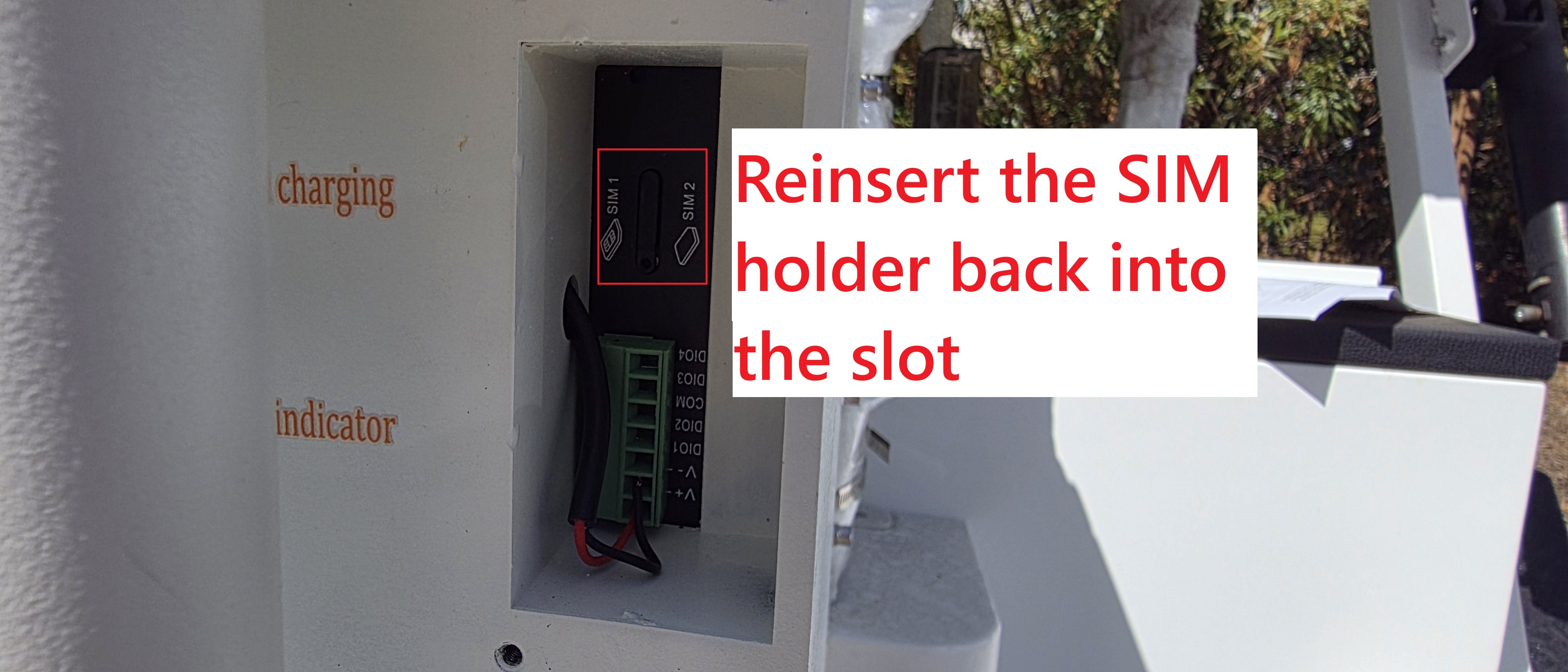
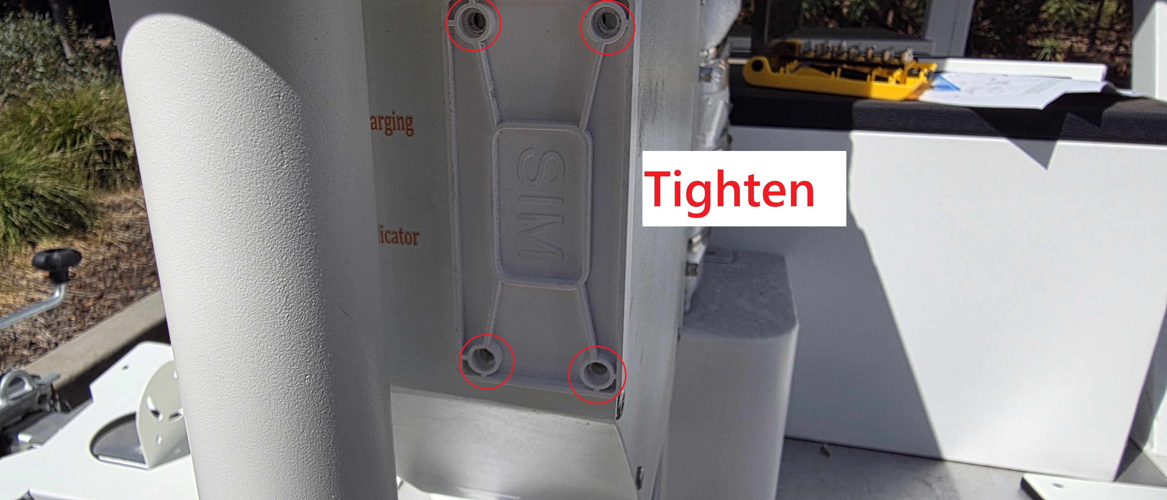
d. Reinsert the holder into the router, and reinstall the cap.
2. Mount the bracket — The pole installation is shown as an example.
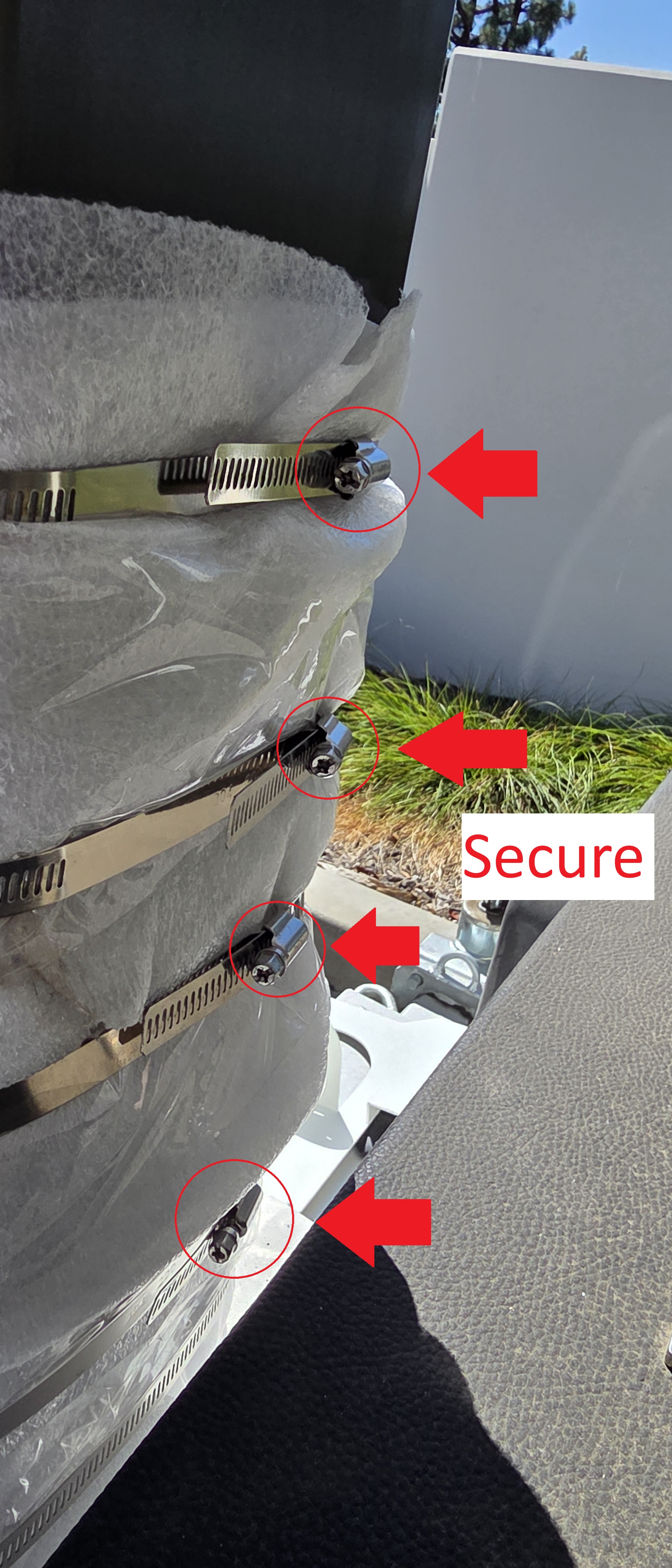
Secure the pole mounting bracket to the pole with the five metal clamps. Use a Phillips screwdriver (not included).
3. Hang the battery box — Hang the battery box onto the pole bracket. The snap-fit holds it in place while you secure the screws. Use the 5 mm hex wrench to tighten the ten M6×16 screws.
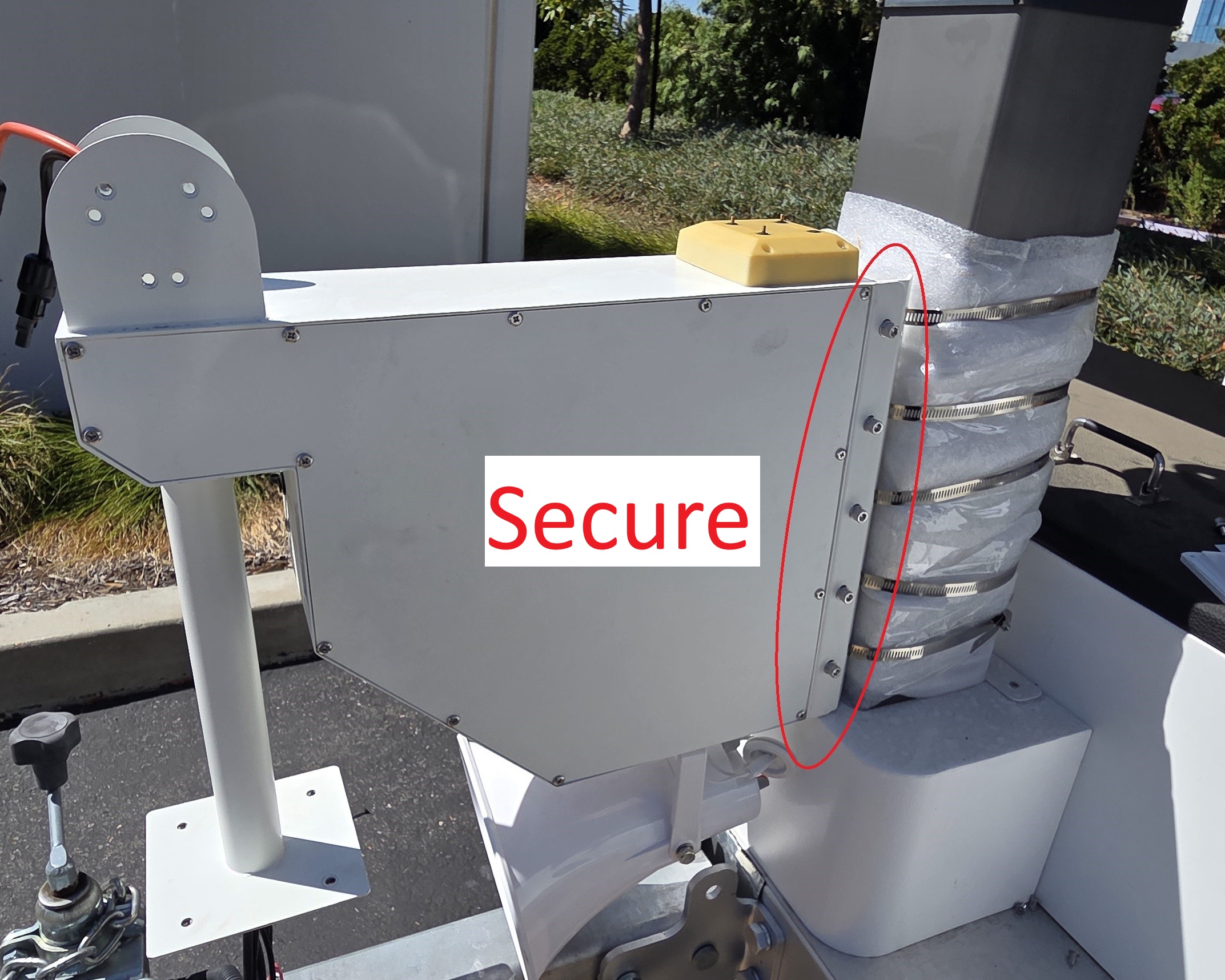
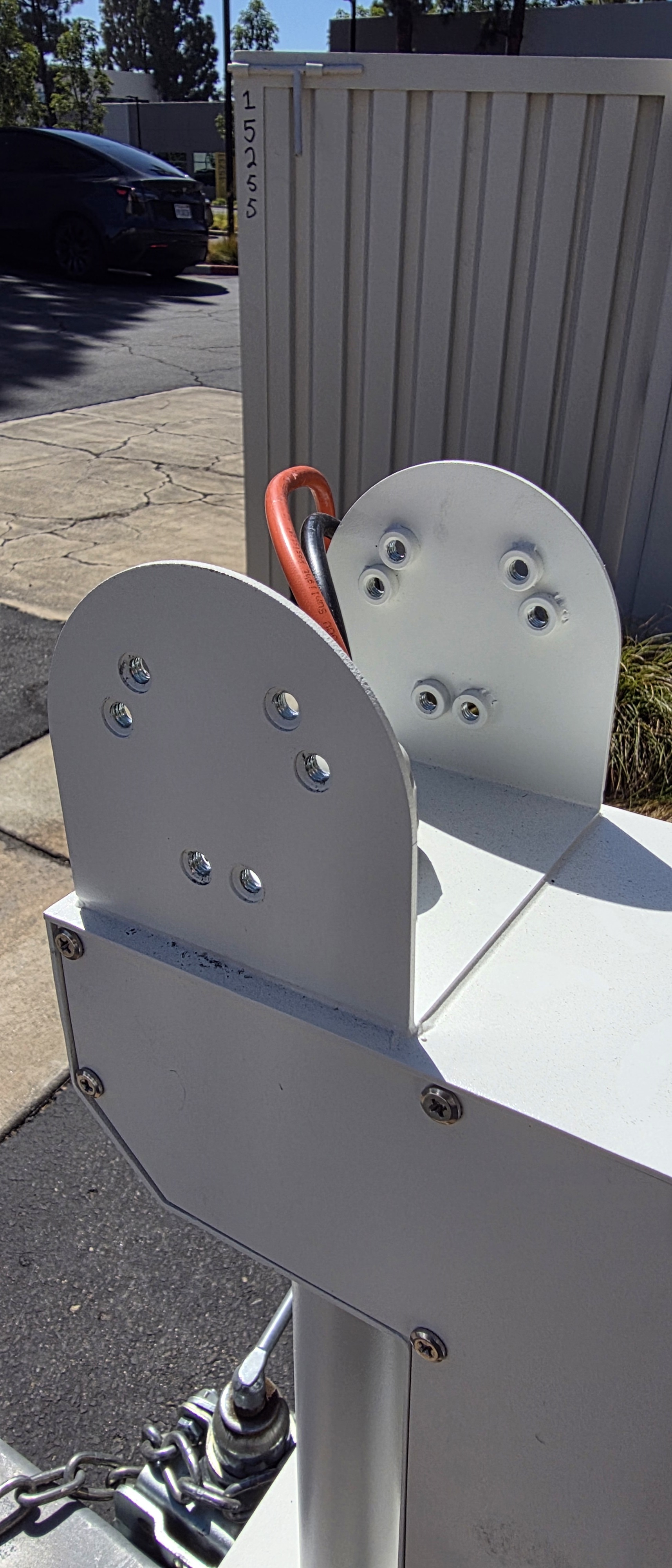
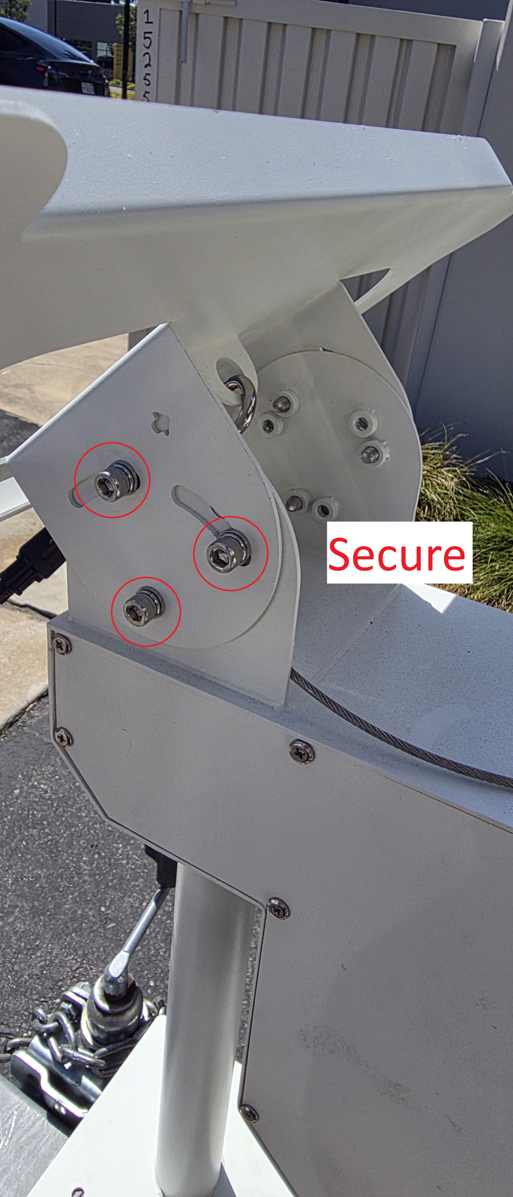
4. Install the PV (Photovoltaic) angle bracket — Install the PV angle bracket on the battery box. Adjust the bracket to between 10° and 75° based on your latitude. Use the 5 mm hex wrench to tighten the six M6×16 screws.
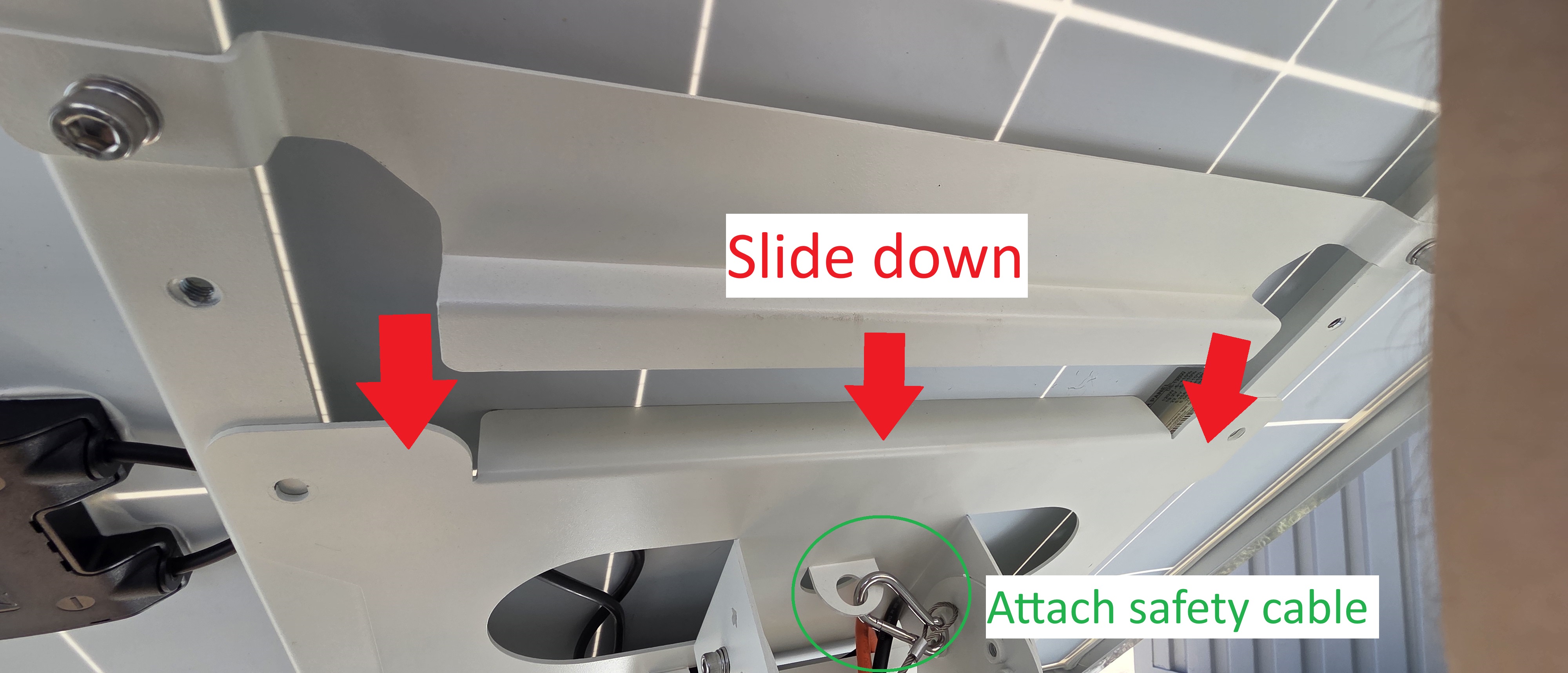
5. Hang the PV module — Attach the safety cable to the PV module. Hang the module onto the PV angle bracket — the snap-fit holds it in place. Use the 5 mm hex wrench to tighten the four M6×16 screws.
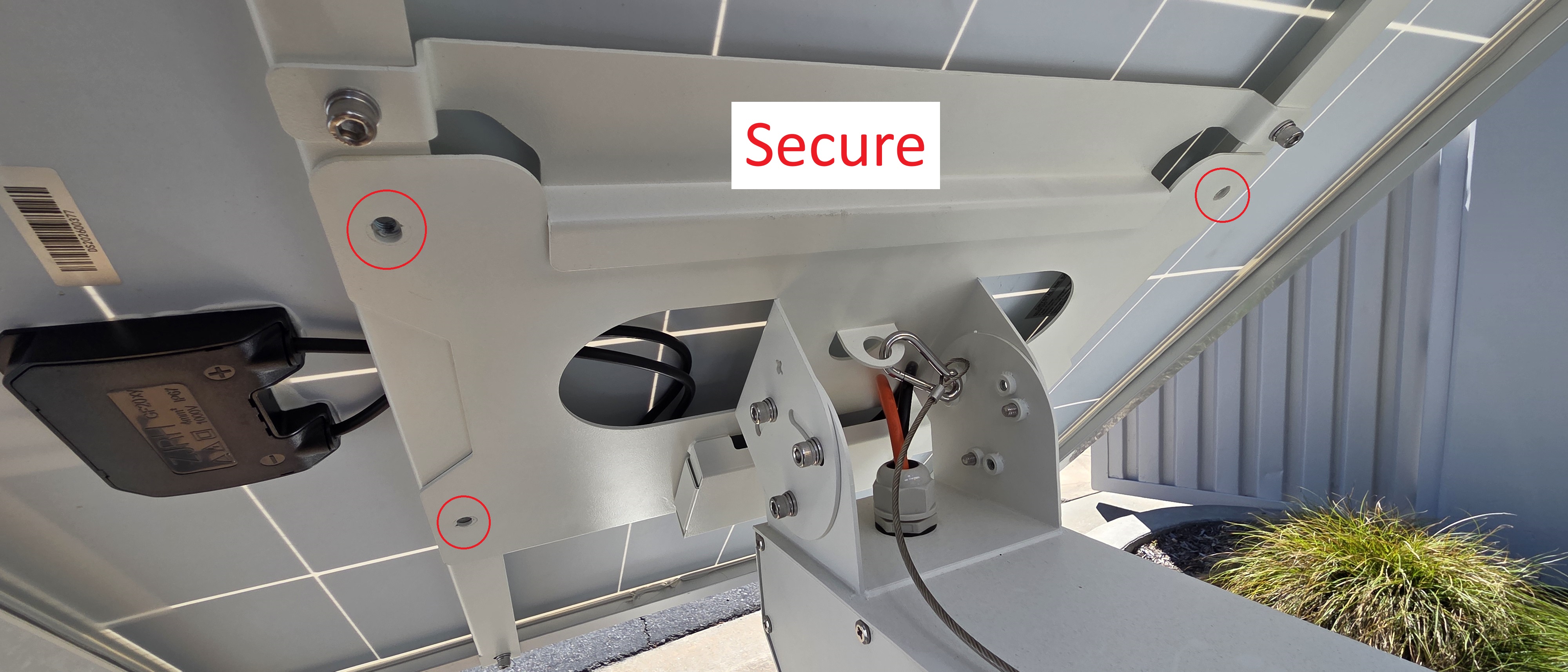
6. Connect the PV wiring — Mate the two sets of MC4 connectors on the PV wiring harness. Place the connectors inside the cable junction box and close the cable cover. Use the 5 mm hex wrench to tighten the M6×16 screw.
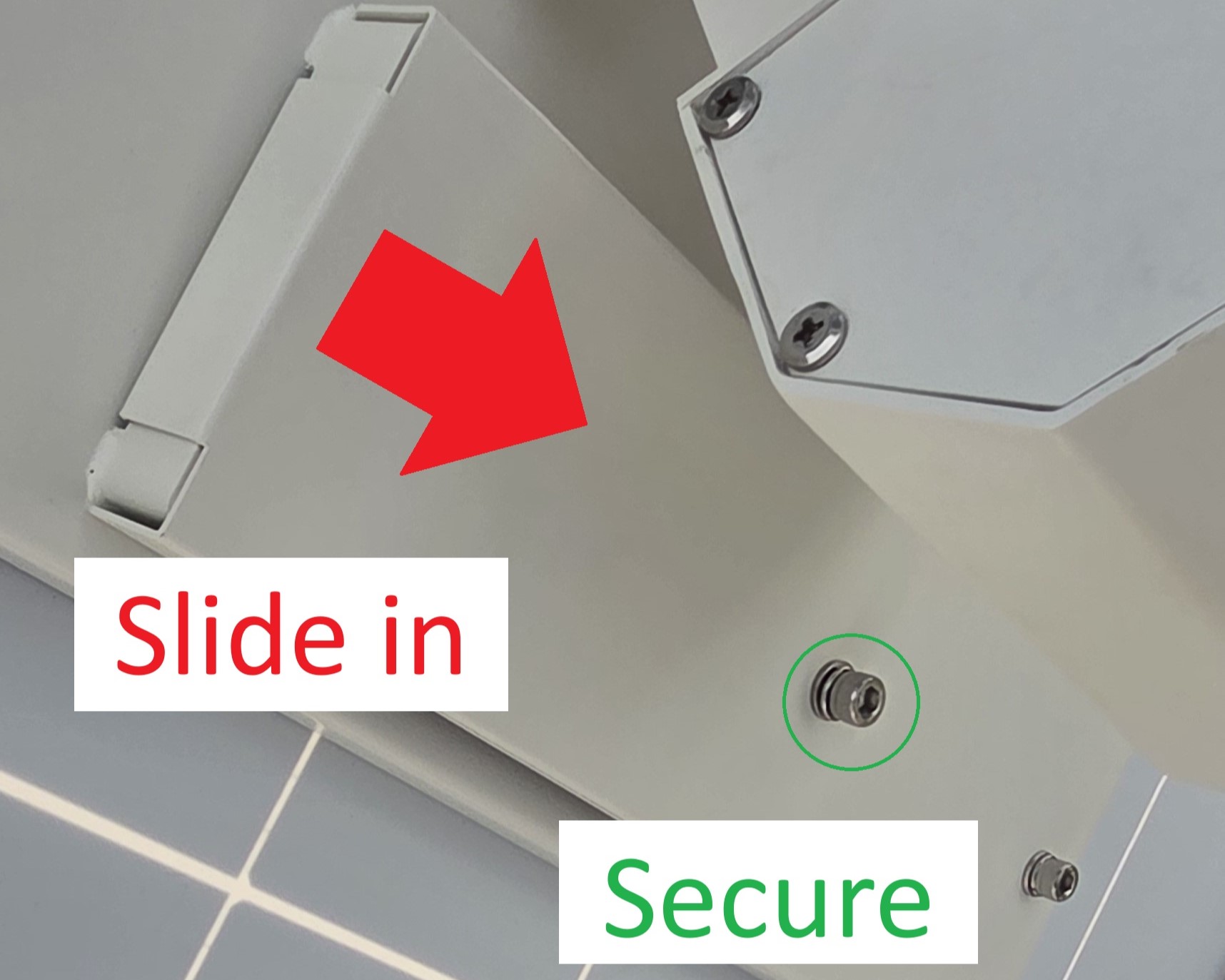
7. Install the speaker — Use the 6 mm hex wrench and three M8×18 screws to secure the speaker to the bottom of the battery box. Connect the speaker's audio and power cables. Tuck the harness connector into the hole at the bottom of the box.
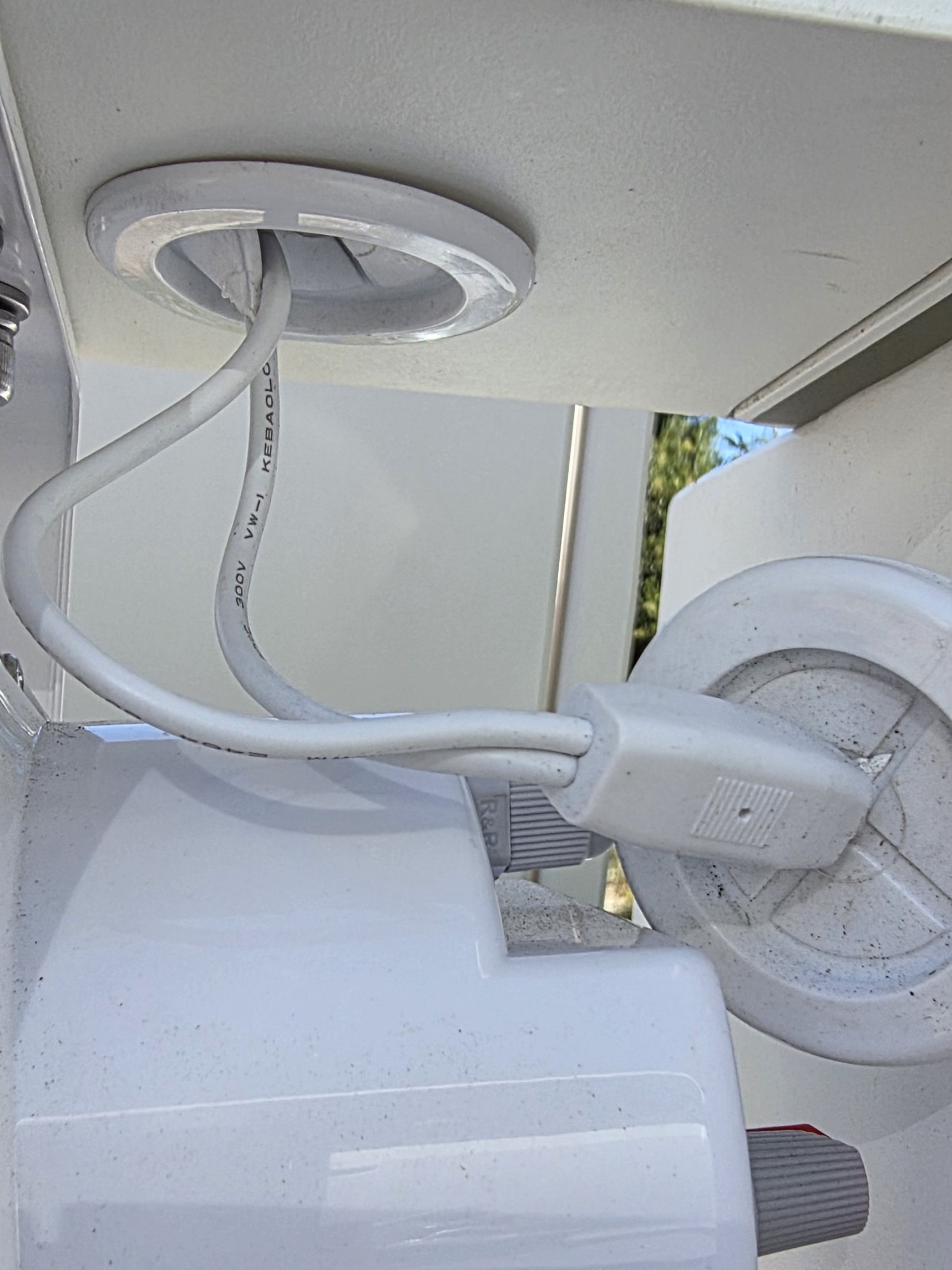
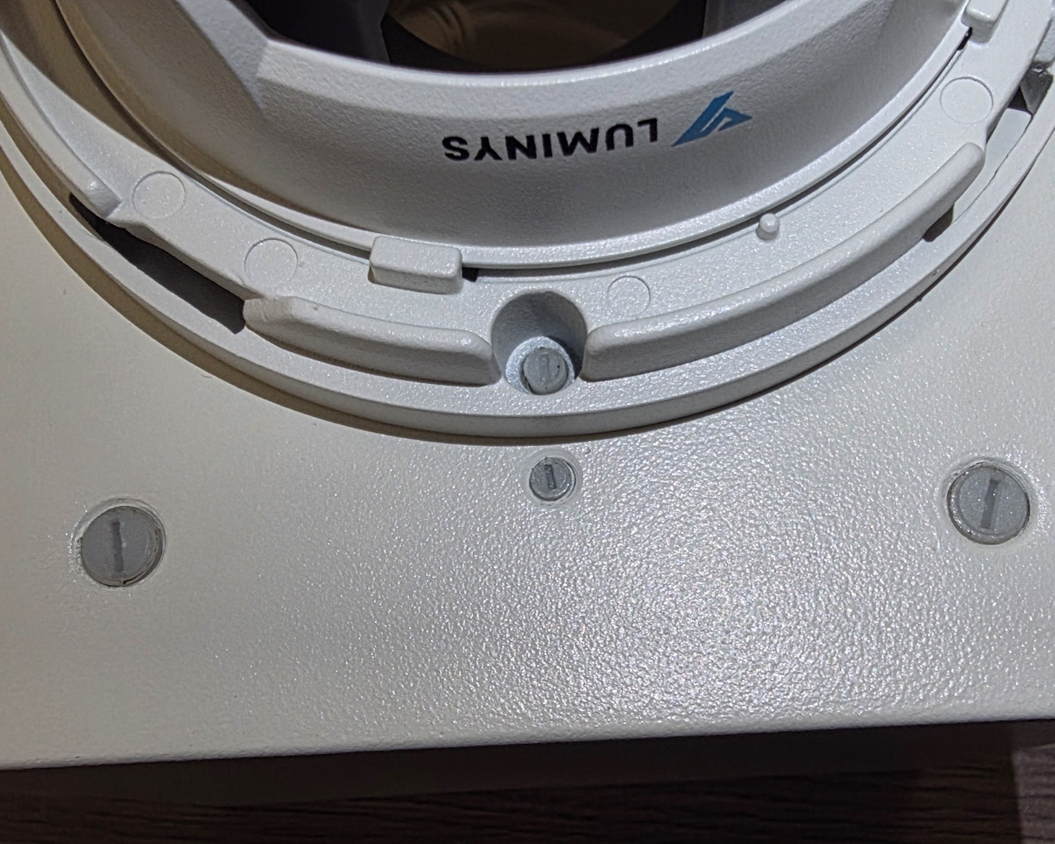
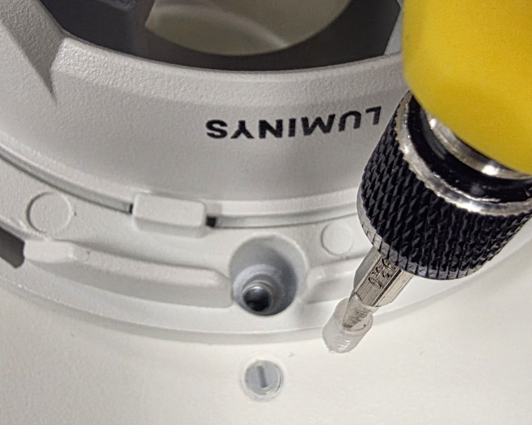
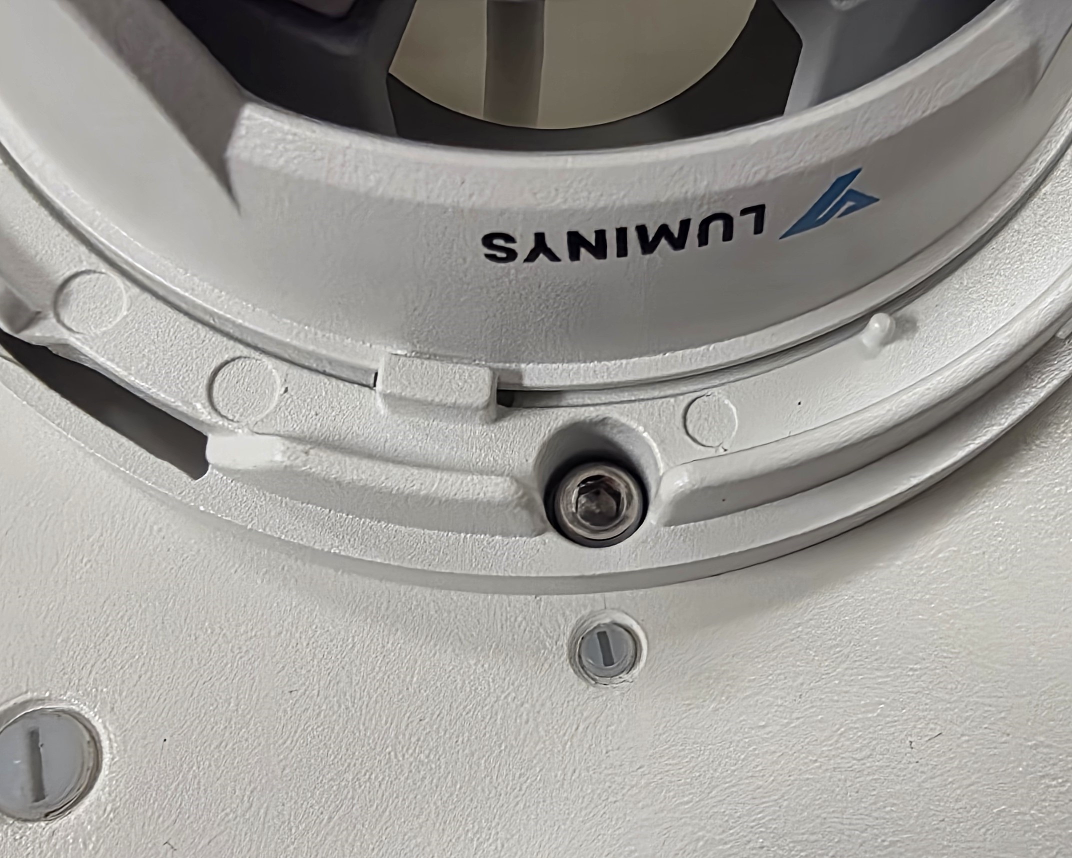
8. Mount the camera — Remove the plastic plugs or screws from the bolt holes on the camera mounting bracket. Mount the camera onto the bracket using the fasteners.
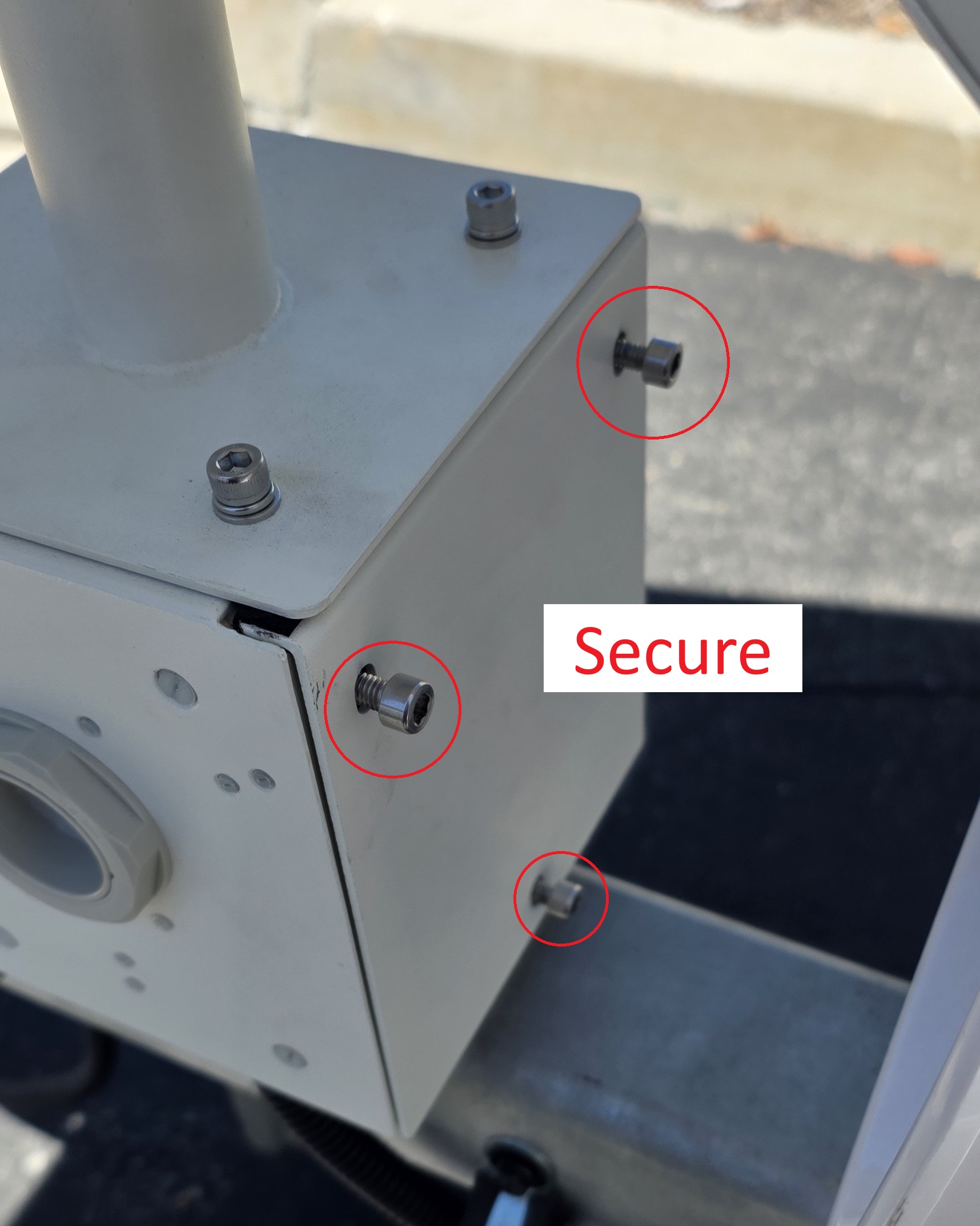
9. Hang the camera assembly — Hang the camera assembly under the round mounting tube of the battery box. The snap-fit holds it in place. Use the 5 mm hex wrench to tighten the four M6×16 screws.
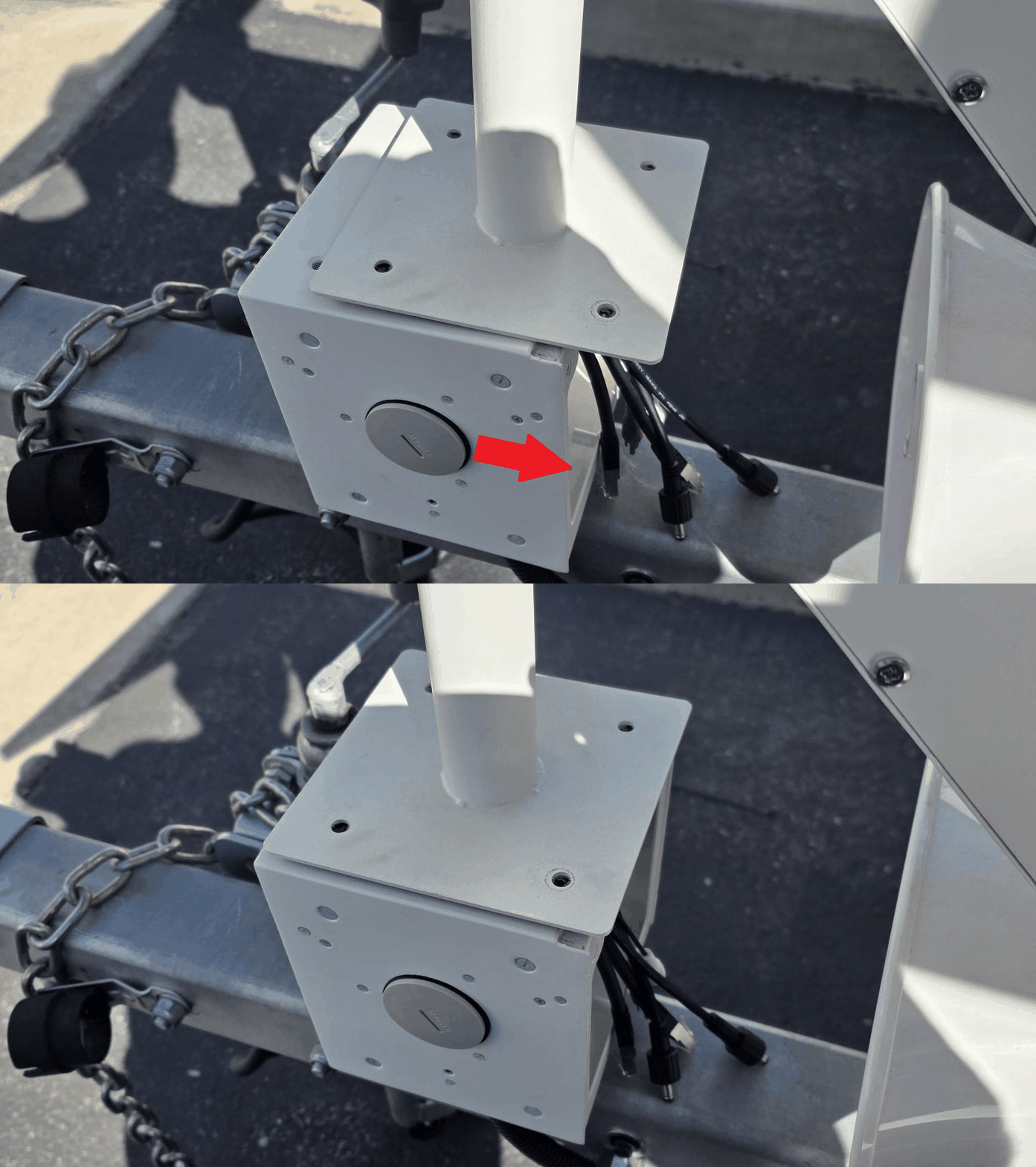
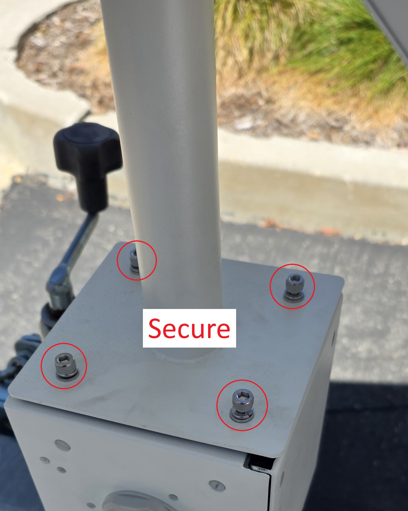
10. Connect the camera cables — Connect the camera's power cable, Ethernet cable, and audio cable. Close the rear cover of the camera mounting bracket. Use the 5 mm hex wrench to tighten the three M6×16 screws.
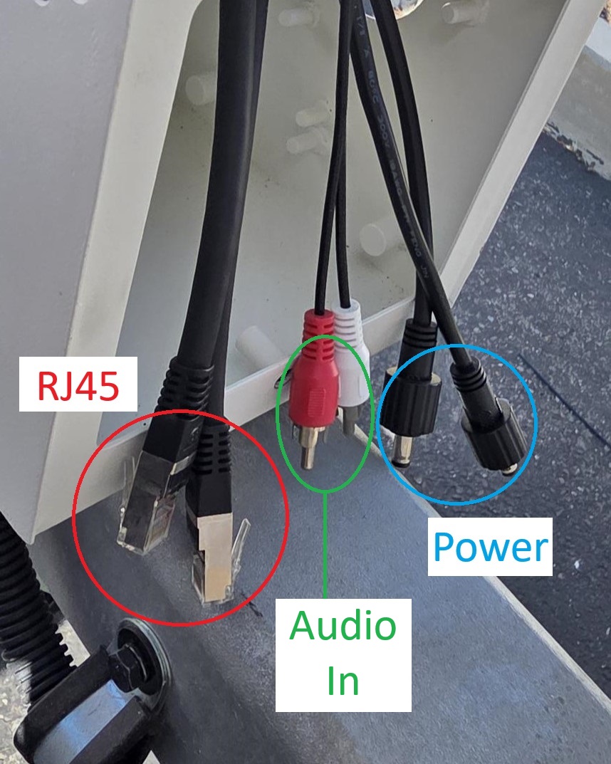
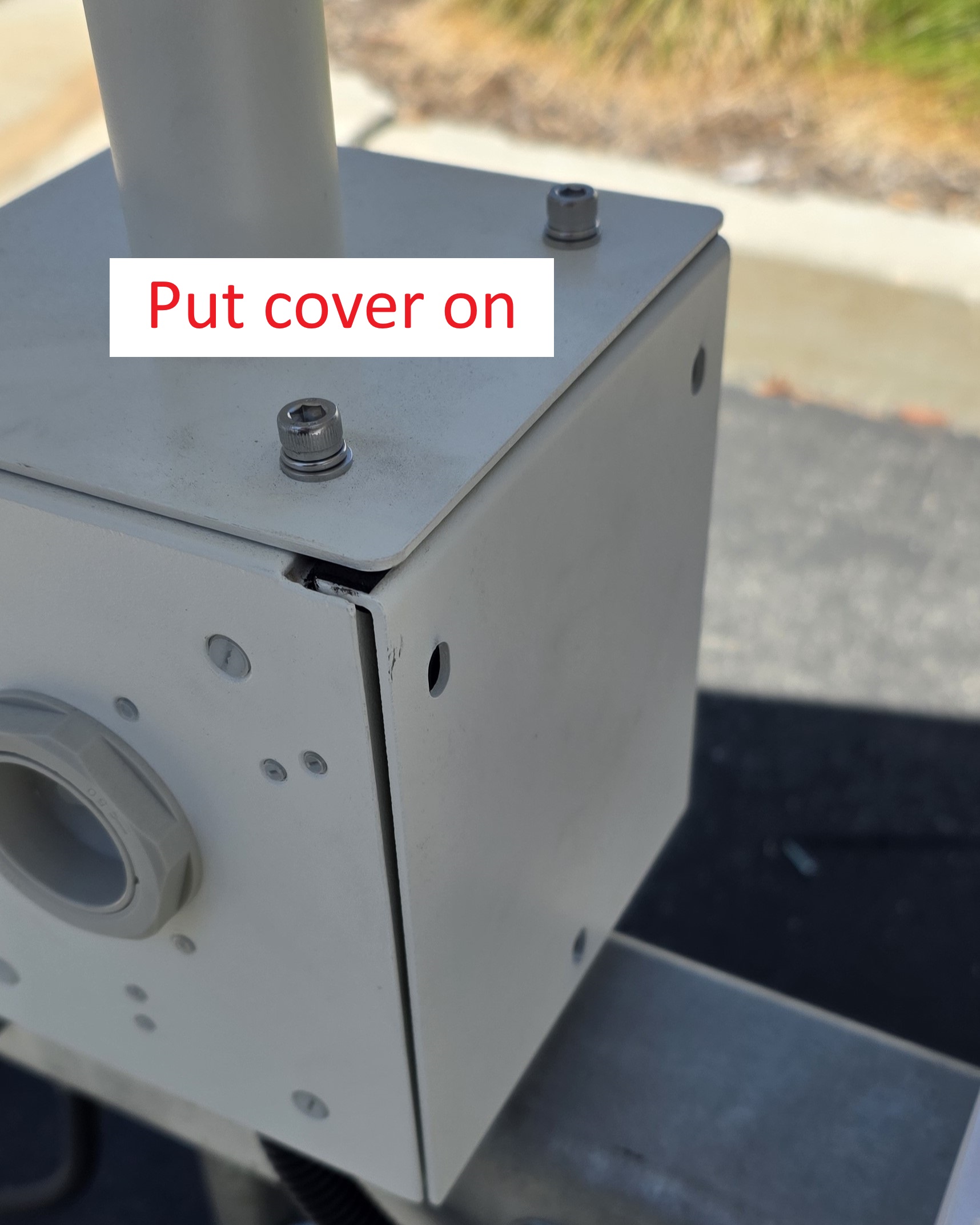
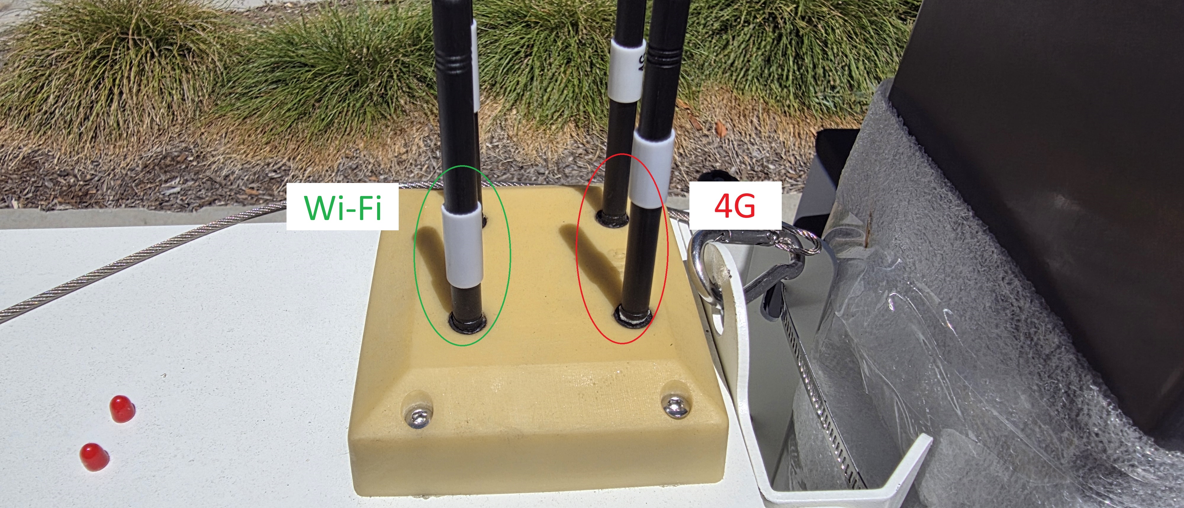
11. Install the antenna — Install the four antennas onto the antenna mount. Match each antenna to its port: two 4G antennas and two Wi-Fi antennas.
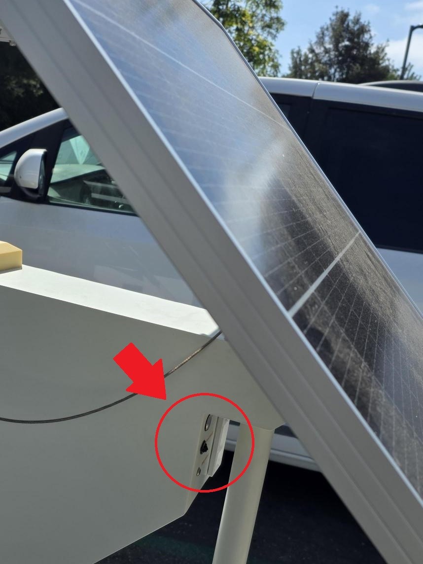
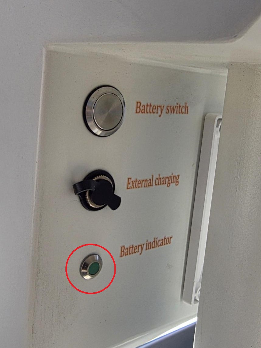
12. Press the battery switch
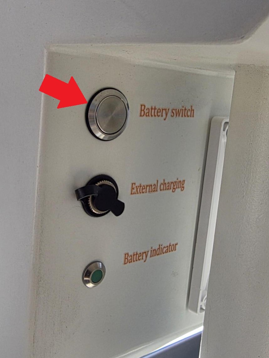
13. Check the battery indicator light against the status table below. If the indicator does not match any listed pattern, contact technical support.
|
|
|
14. You can power the unit from a wall outlet through the external charging port using an AC-DC adapter. Do not use an AC-output adapter — the unit requires DC. The plug must measure 5.5 mm outer diameter / 2.5 mm inner diameter, center positive. Use a 24 VDC / 5 A adapter.