Access Control/Wiring of the Reader and Controller: Difference between revisions
From Luminys WIKI
Techsupport (talk | contribs) No edit summary |
Techsupport (talk | contribs) No edit summary |
||
| Line 1: | Line 1: | ||
<div class="lm-banner">[[File:LuminysMainPageBanner2.png]]</div> | <div class="lm-banner">[[File:LuminysMainPageBanner2.png]]</div> | ||
= <div class="center"> | = <div class="center">Wiring of the Reader and Controller</div> = | ||
===Description=== | ===Description=== | ||
Revision as of 15:59, 14 November 2024
Wiring of the Reader and Controller
Description
This tutorial will go over some information regarding Analytics.
Prerequisites
- Knowledge about Analytics
Video Instructions
Coming soon
Step by Step Instructions
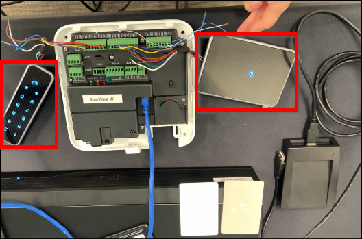
1. In the following wiring example, two readers are connected via RS485 to access control.
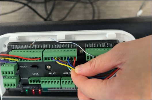
2. Match the wires of the reader and connect them to the corresponding contacts of the access control.
Purple = 485A
Yellow = 485B
Brown = LED1
Blue = CASE
Black = GND
Red = 12V
Note: For third-party readers, Wiegand connections are supported.


