LumiGuardian/LumiGuardian Initial Setup
LumiGuardian Inital Setup
Description
This article will cover:
- How to physically setup LumiGuardian
- How to create a LumiCloud User Account via the LumiCloud Partner Portal
- How to complete the setup process for a new LumiCloud User Account
- How a LumiCloud Partner Account can add a LumiGuardian device to a LumiCloud User Account
- How to allocate licenses via the LumiCloud Partner Portal
Prerequisites
- A computer with a web browser
- LumiCloud Partner Account setup
- A LumiGuardian Device
- LumiCloud Solar Trailer License
- LumiCloud 4G Data License
Purchasing Information (Talk to a Sales Rep for more information):
| Model | Description |
|---|---|
| TG-113A | LumiGuardian Solar Security Trailer (without cameras) |
| LCL-ST4 | LumiCloud Solar Trailer License (Max 4 Channels) |
| TG-113A-S | Ground Shipping |
| LCL-DATA10GU | LumiCloud 4G Data 10GB (USA Only) |
| LCL-DATA100GU | LumiCloud 4G Data 100GB (USA Only) |
| LCL-DATA200GU | LumiCloud 4G Data 200GB (USA Only) |
| LCL-DATA10GC | LumiCloud 4G Data 10GB (Canada Only) |
| LCL-DATA100GC | LumiCloud 4G Data 100GB (Canada Only) |
| LCL-DATA200GC | LumiCloud 4G Data 200GB (Canada Only)
Quick Links Part 1: Physical Setup
Part 1: Physical SetupVideo Instructions
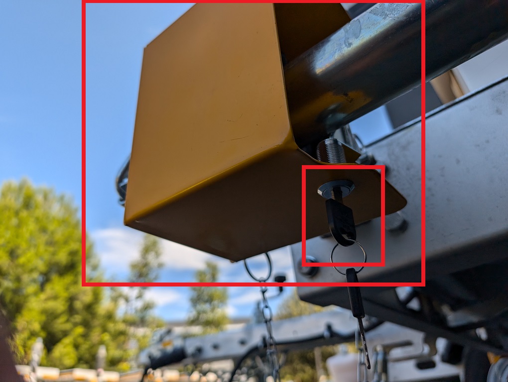
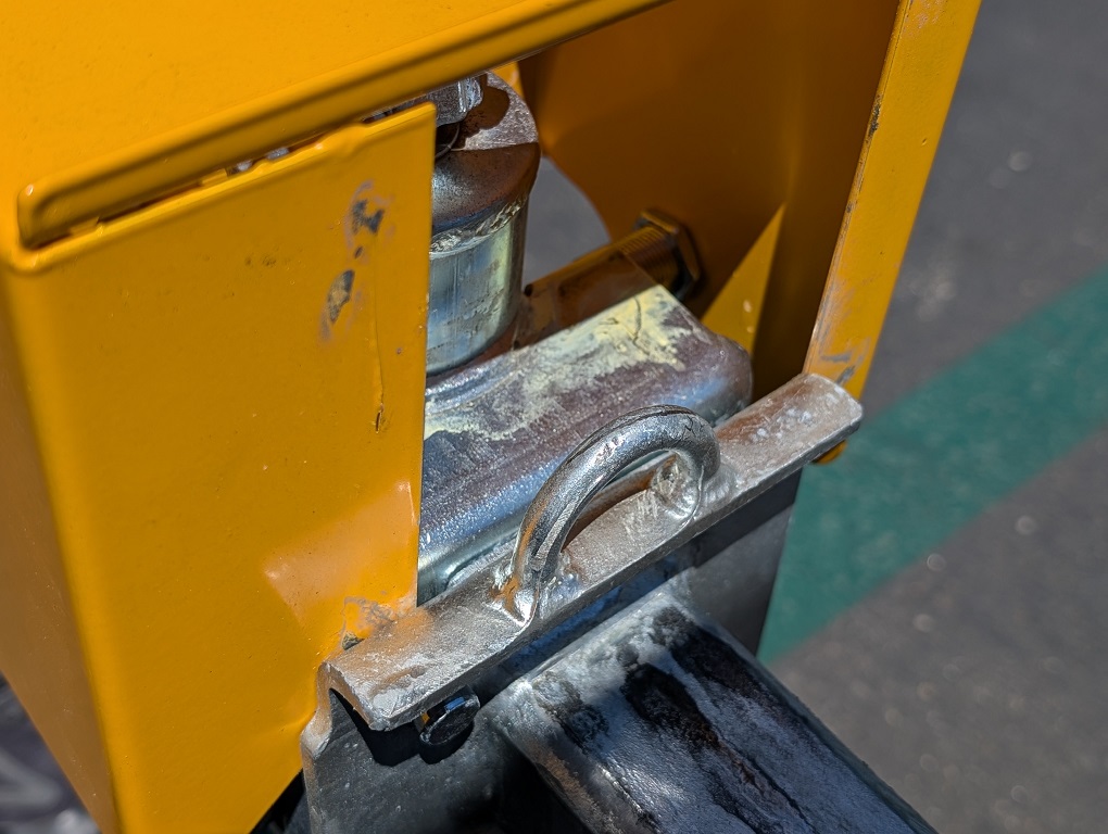
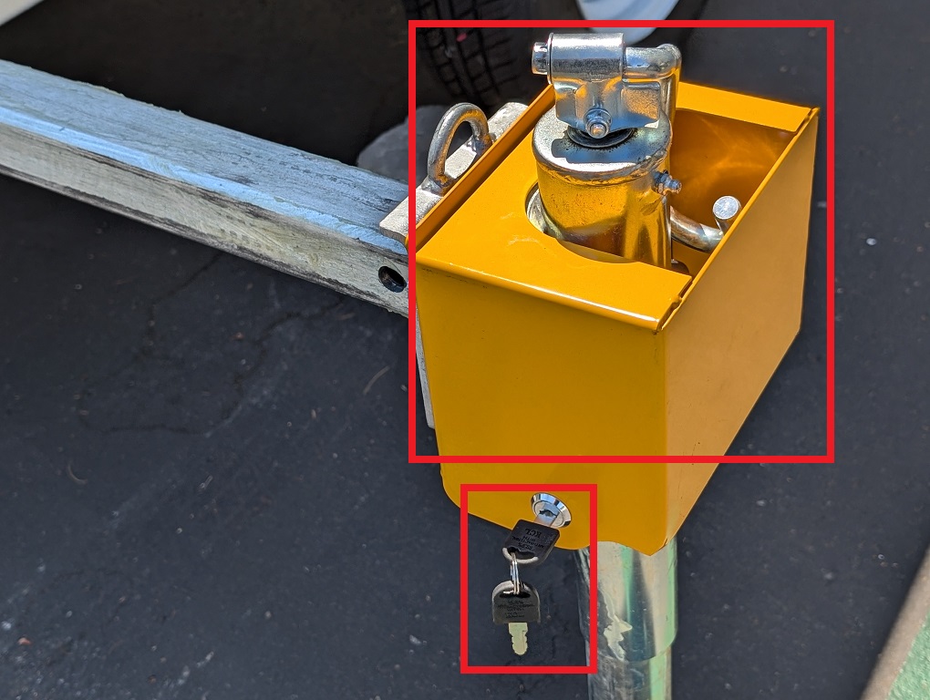
Step by Step Instructions1. Unlock the support access with the attached keys and remove it from the support.
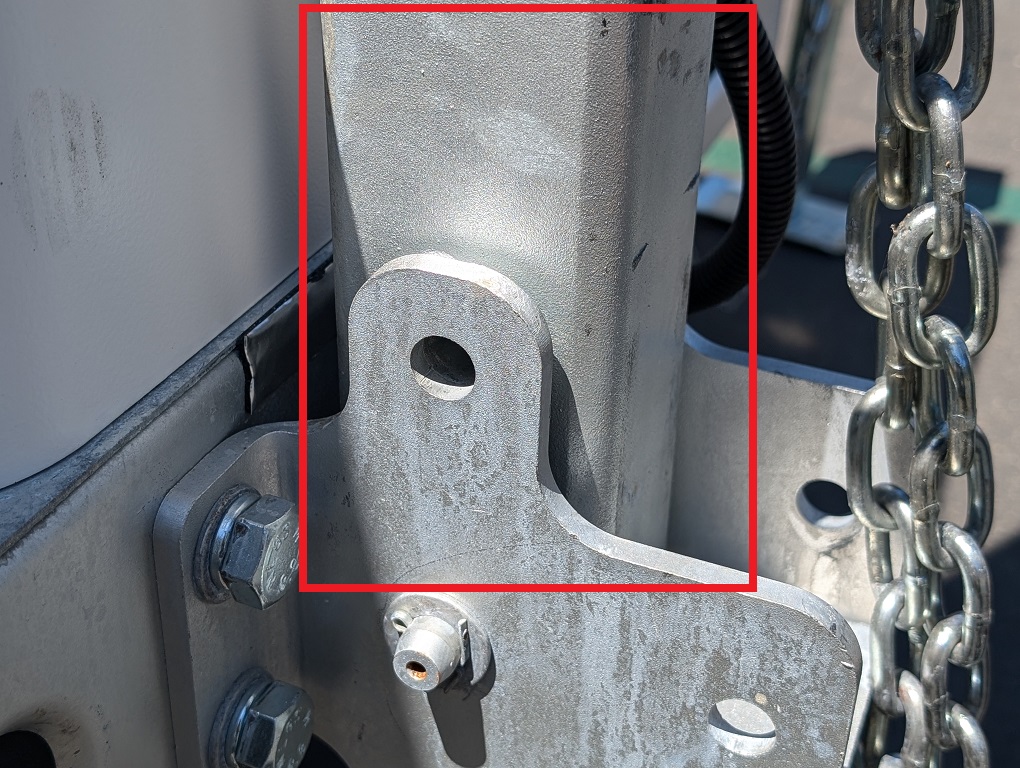
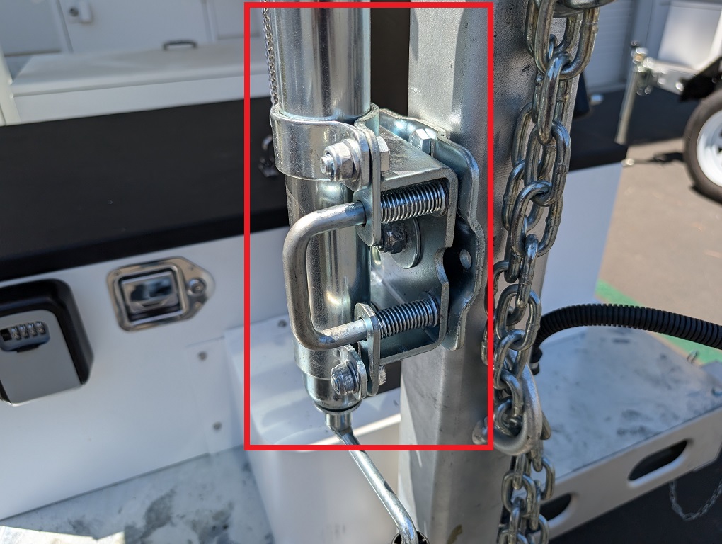
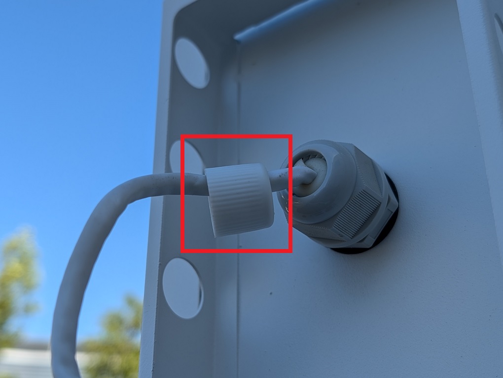
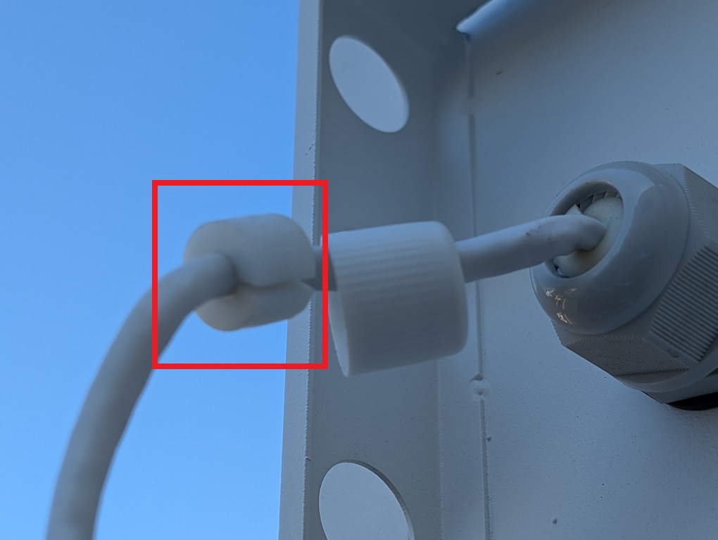
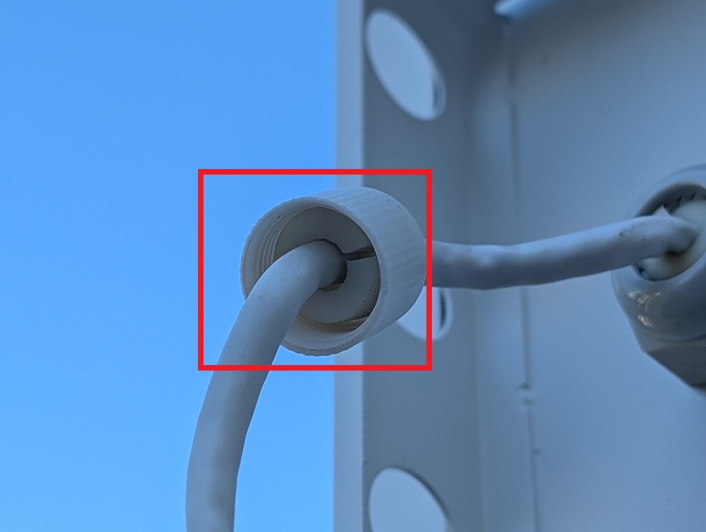
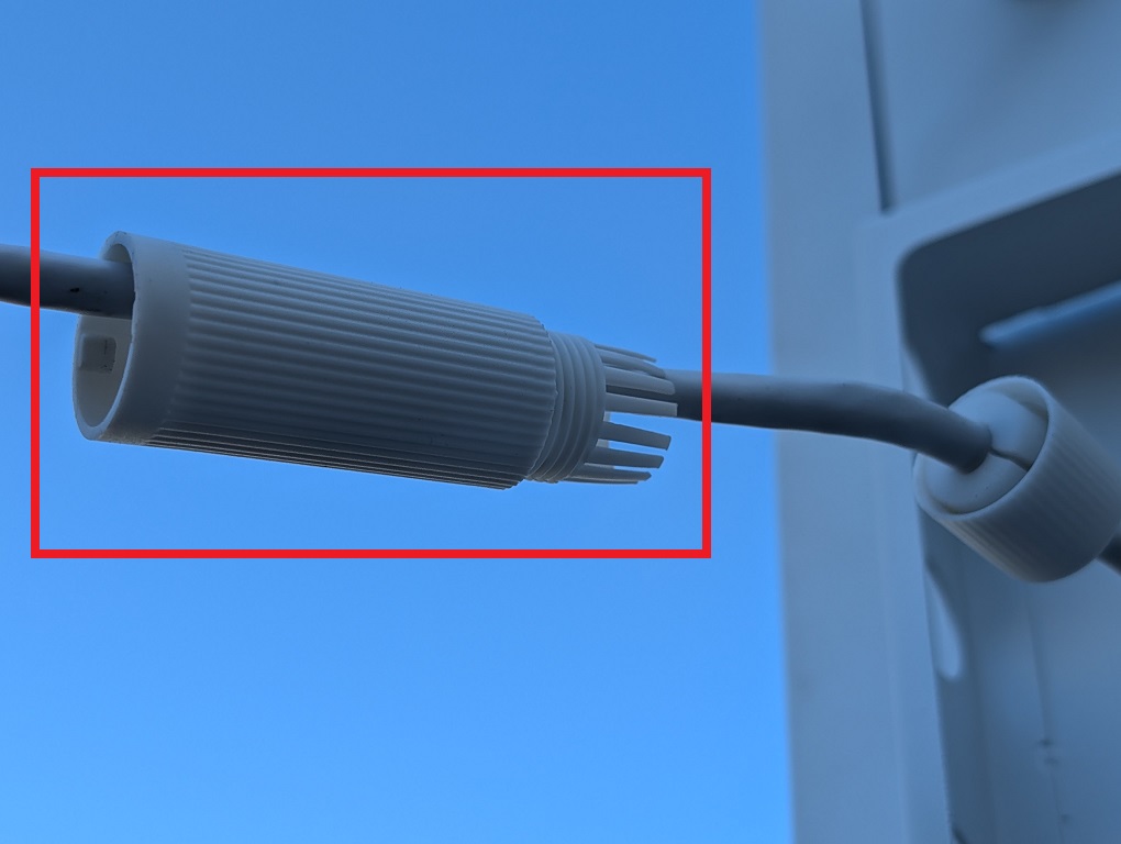
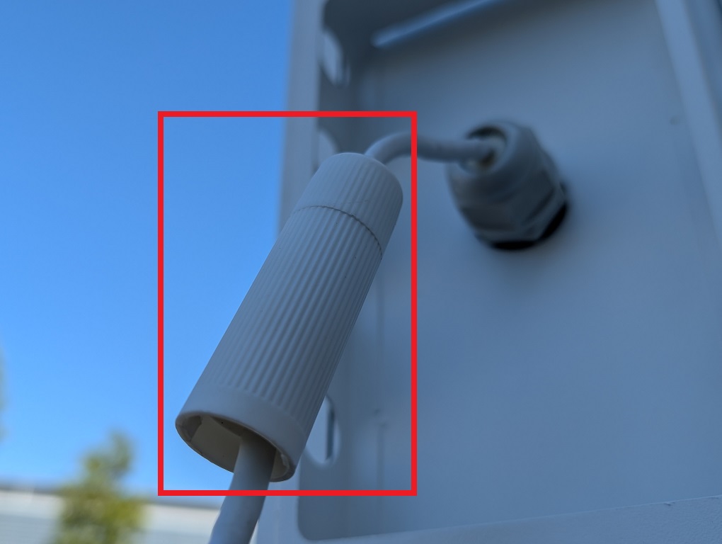
2. Pull out and hold the hook-like metal bolt and turn the support clockwise until the bolt can reach the hole on the other side and lock in place. Then release the bolt.
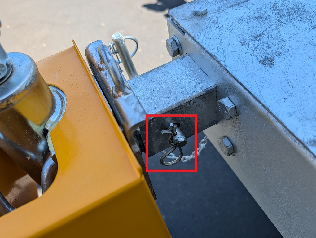
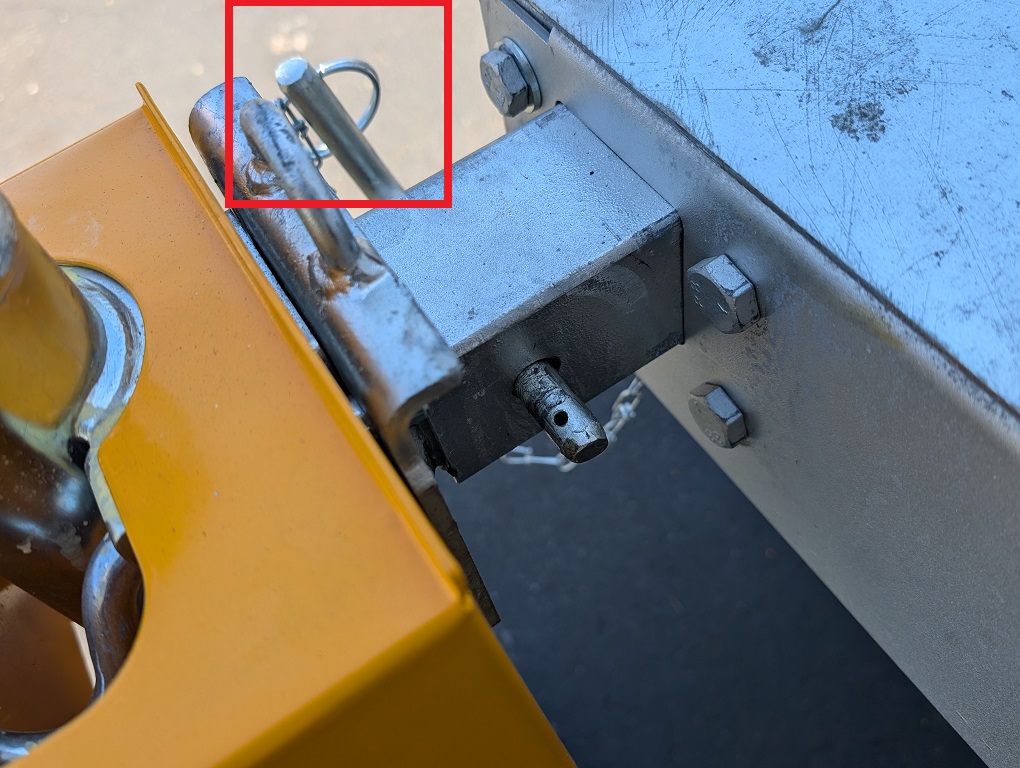
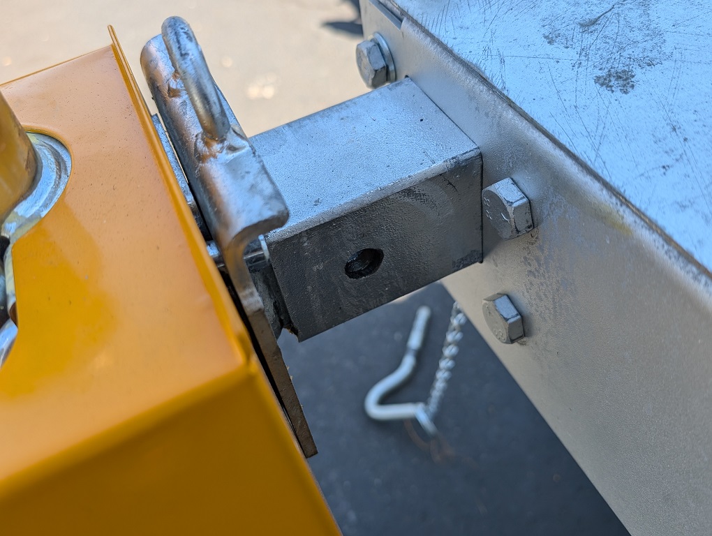
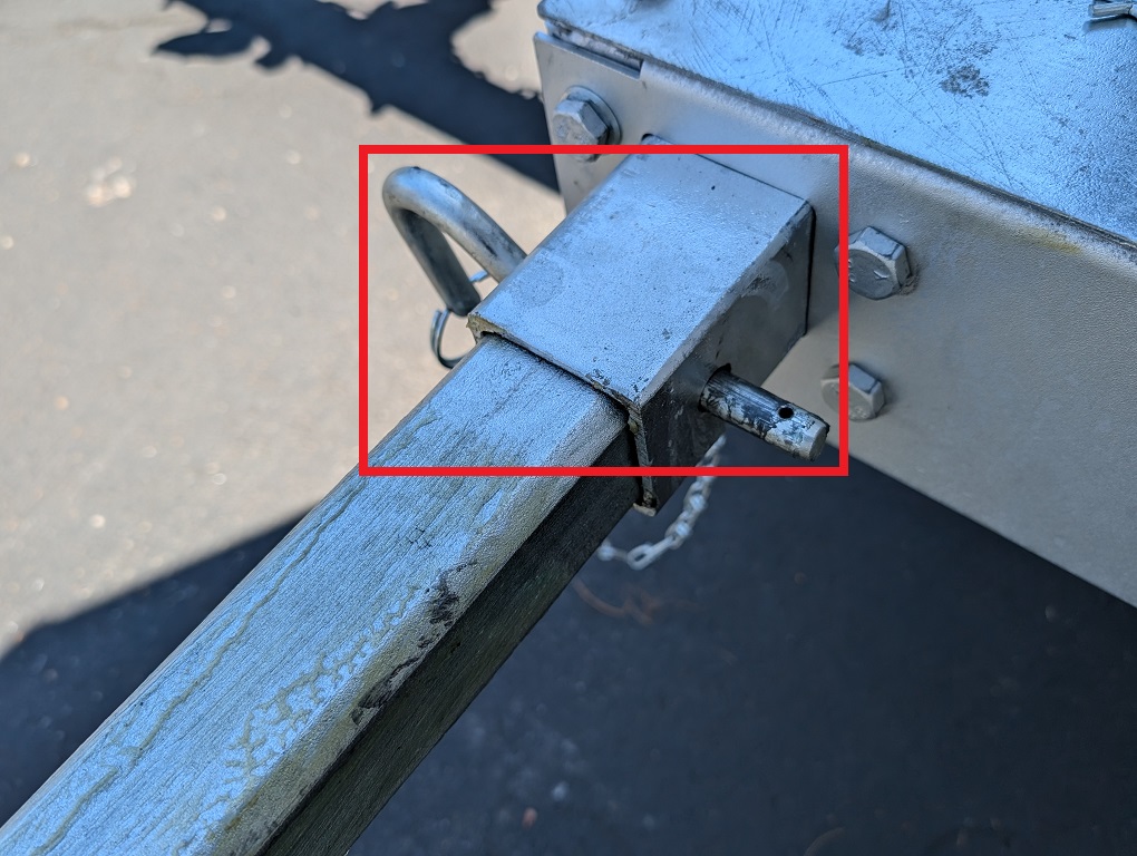
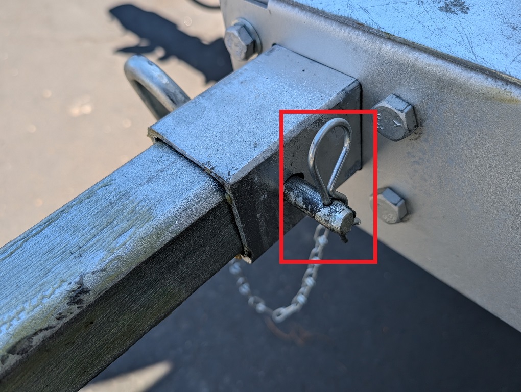
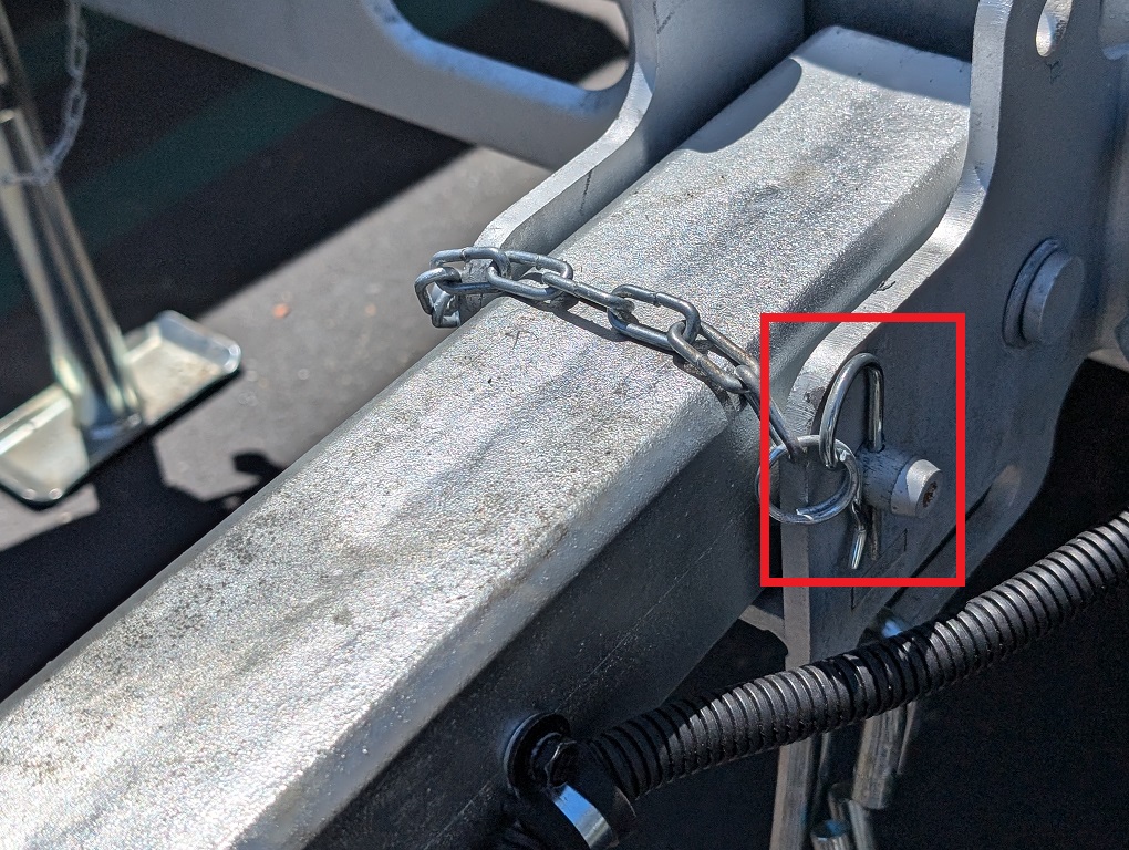
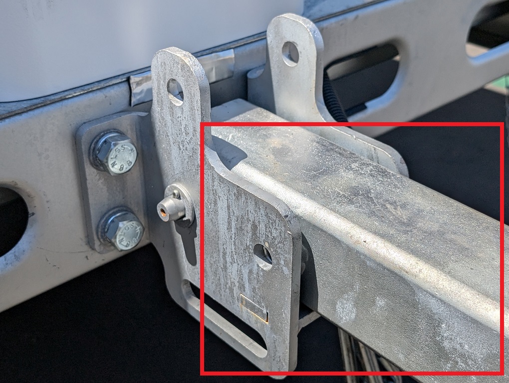
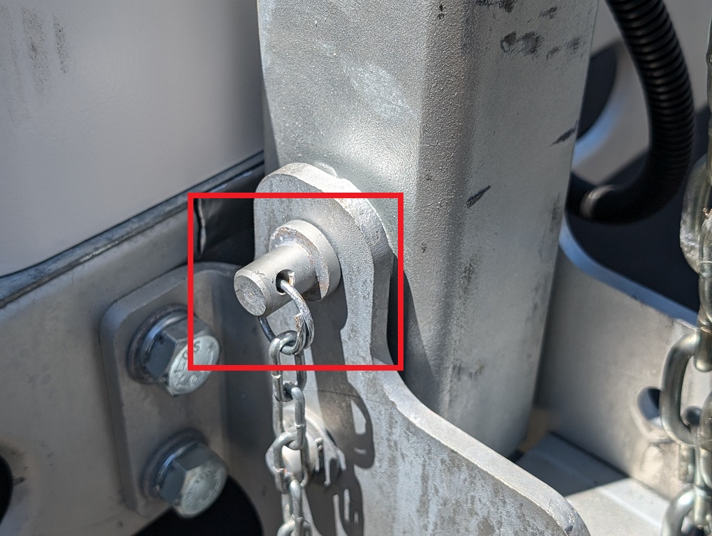
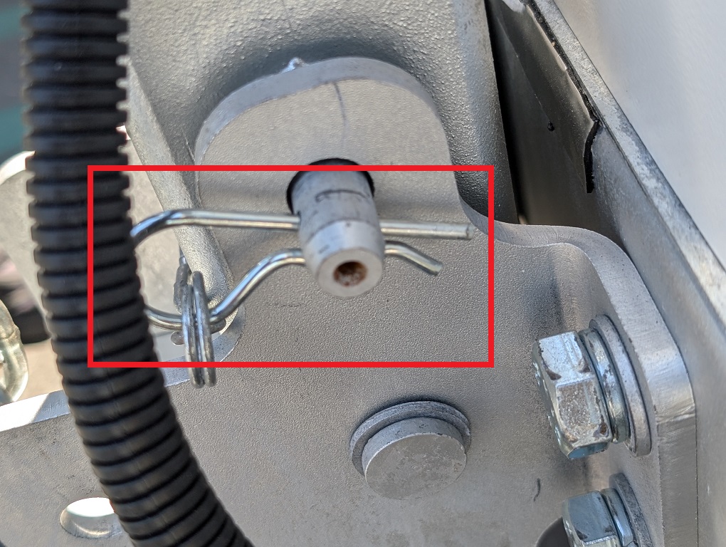
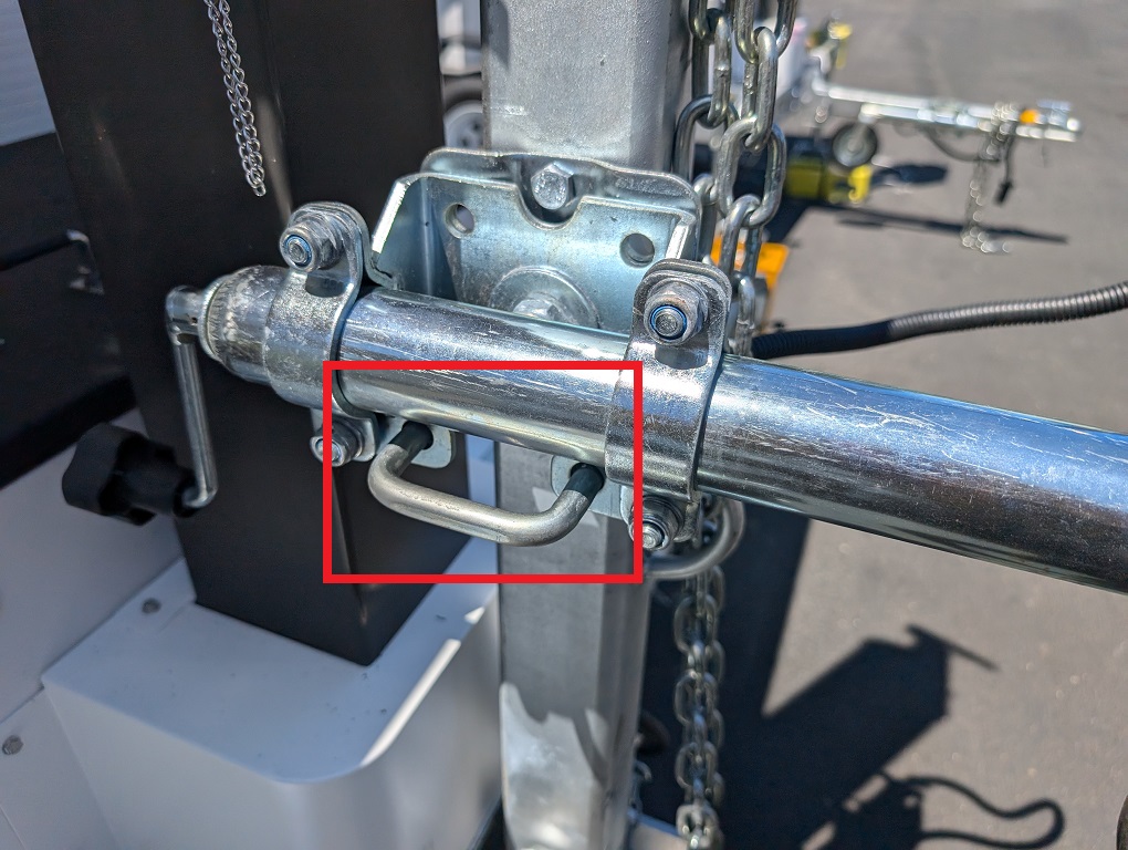
3. Pull out the curved pin, then remove the metal bolt to unlock the support.
4. Once unlocked, pull out the support and lock it again with the metal bolt and curved pin.
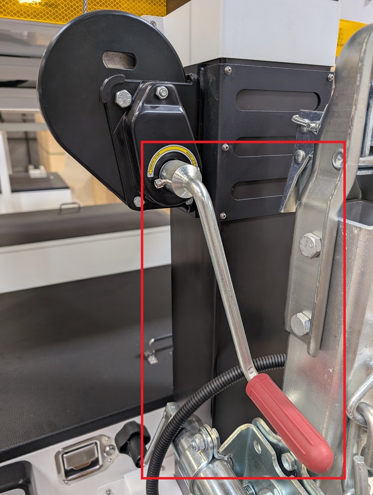
5. Rotate the hand crank clockwise to raise the LumiGuardian trailer and secure it in place.
6. Store the hand crank. Then replace the yellow support access and lock it back into position with the keys.
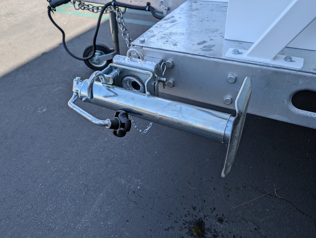
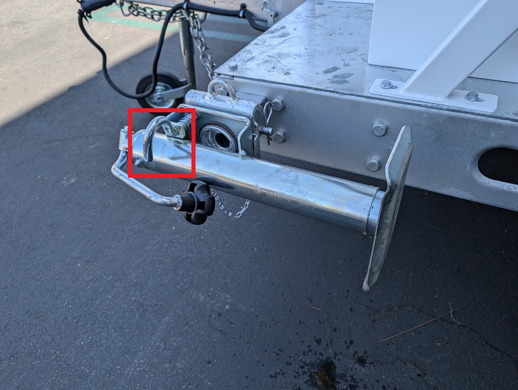
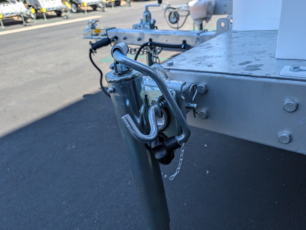
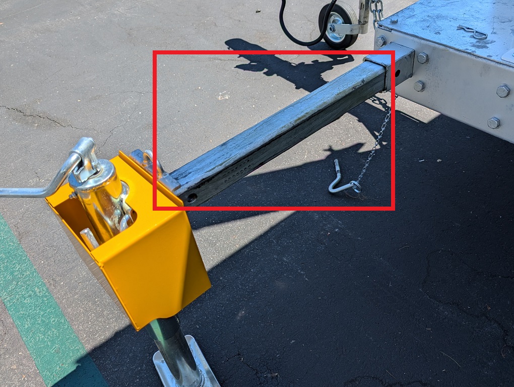
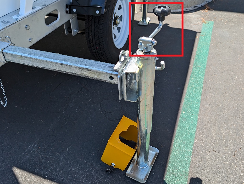
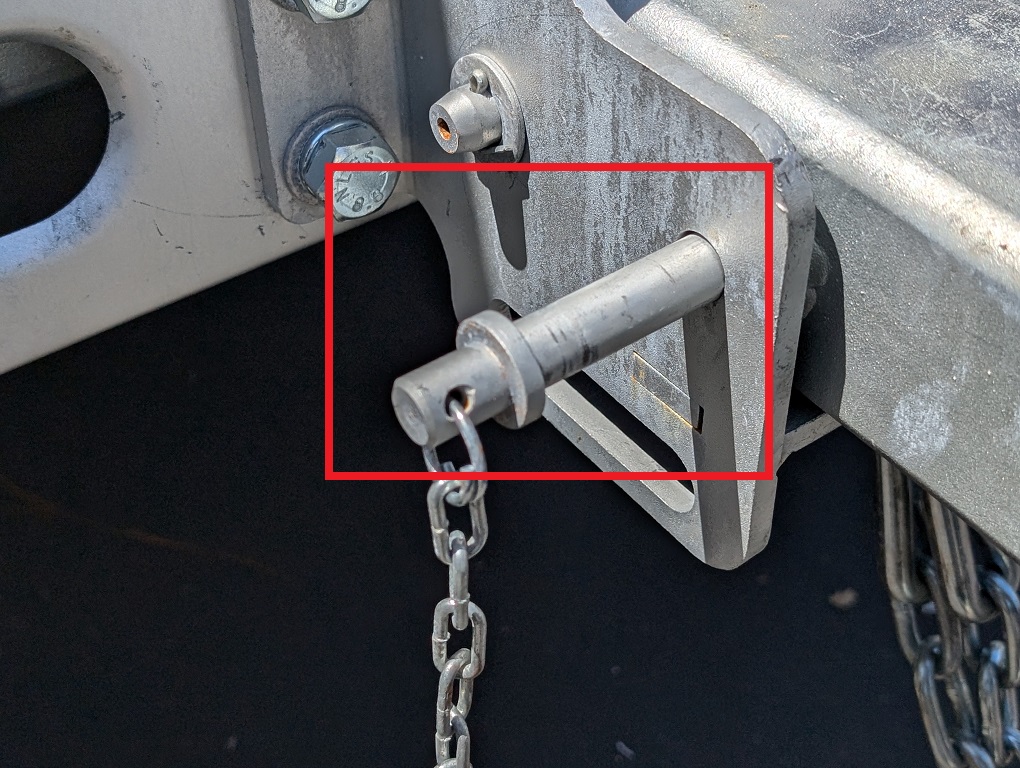
7. Repeat Steps 1 - 6 for the other 3 support arms. 8. Unlock the curved pin from the tow arm and remove the metal bolt. Lift the tow arm and stabilize it in place. Once it's stabilized, re-secure it with the metal bolt and curved pin.
9. To lift the wheel, pull and hold the metal handle out while raising the wheel. Once the wheel is lifted, release the handle to allow it to fall back into the lock mechanism.
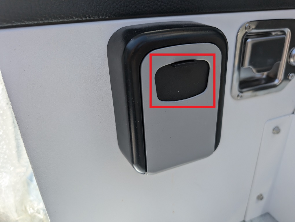
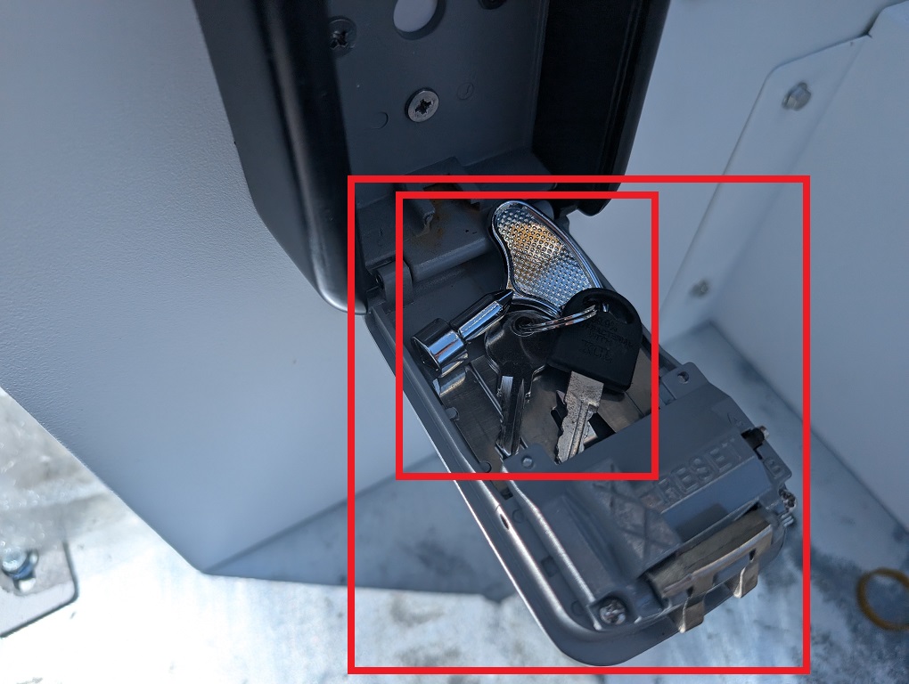
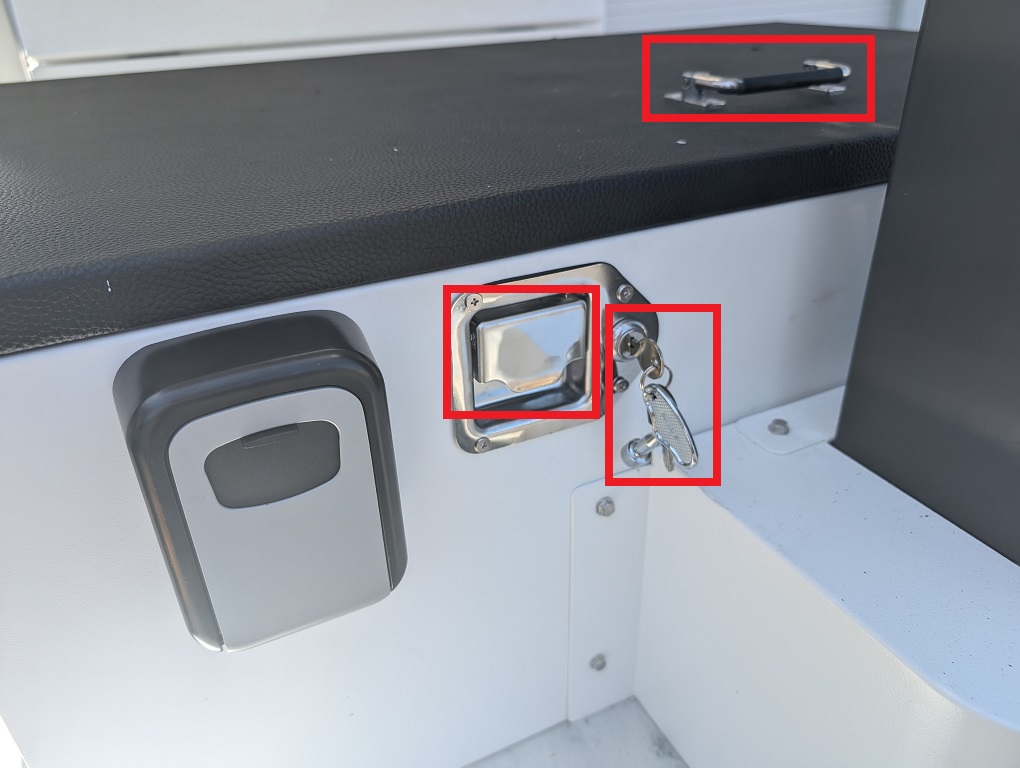
10. Pull down the black cover on the lockbox to reveal the keypad.
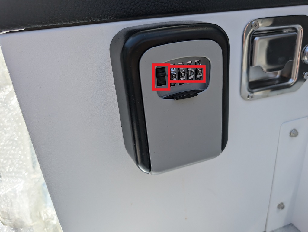
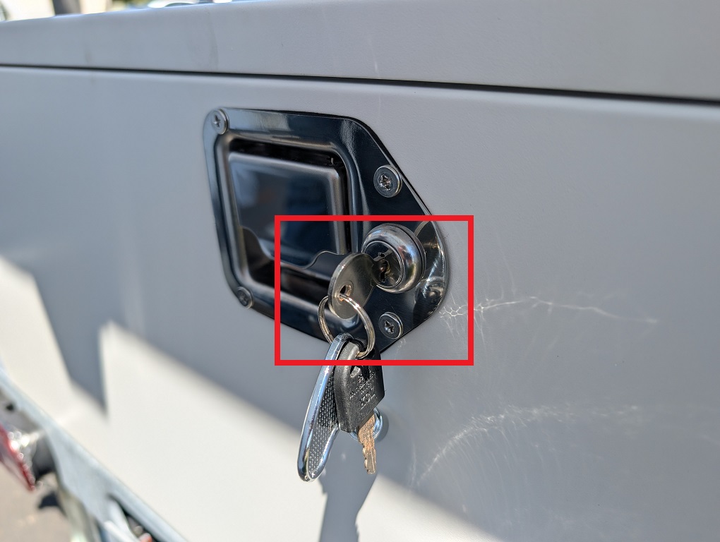
11. Set the dials to the default key code of 0000. To unlock the lockbox, use one hand to pull down the left black handle and the other hand to pull the bottom black cover outward. Inside are the 3 keys for the storage box, electrical box, support access, and control box.
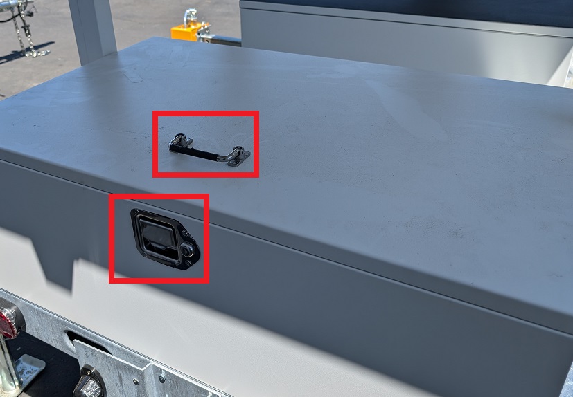
12. Unlock the storage box using the silver metal key. Pull and hold the metal handle outward with one hand, while using the other hand to lift the plastic black handle upward to open the storage box.
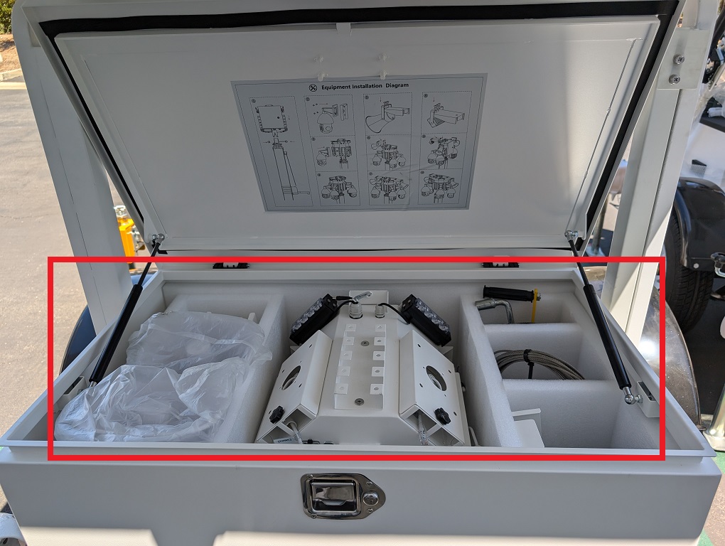
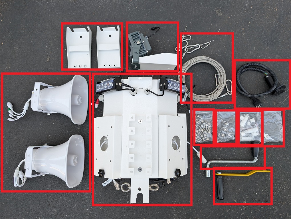
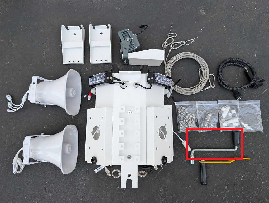
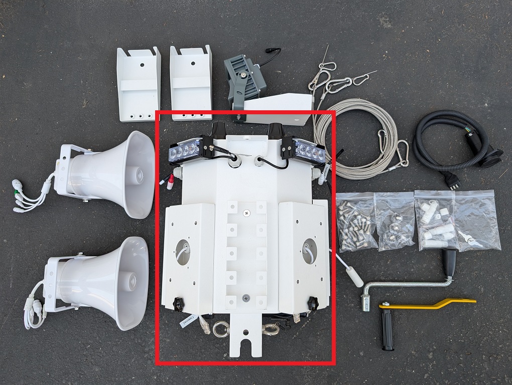
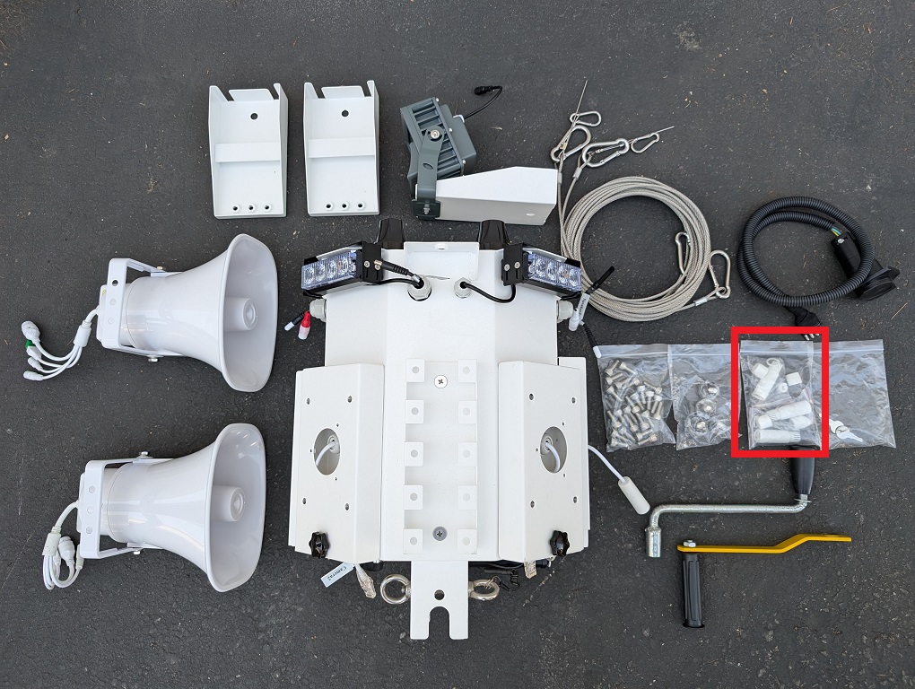
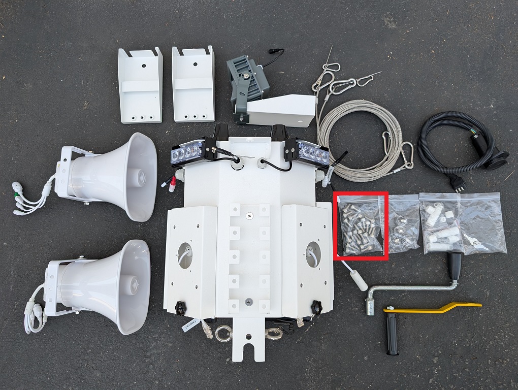
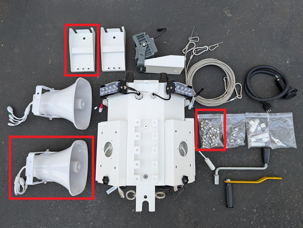
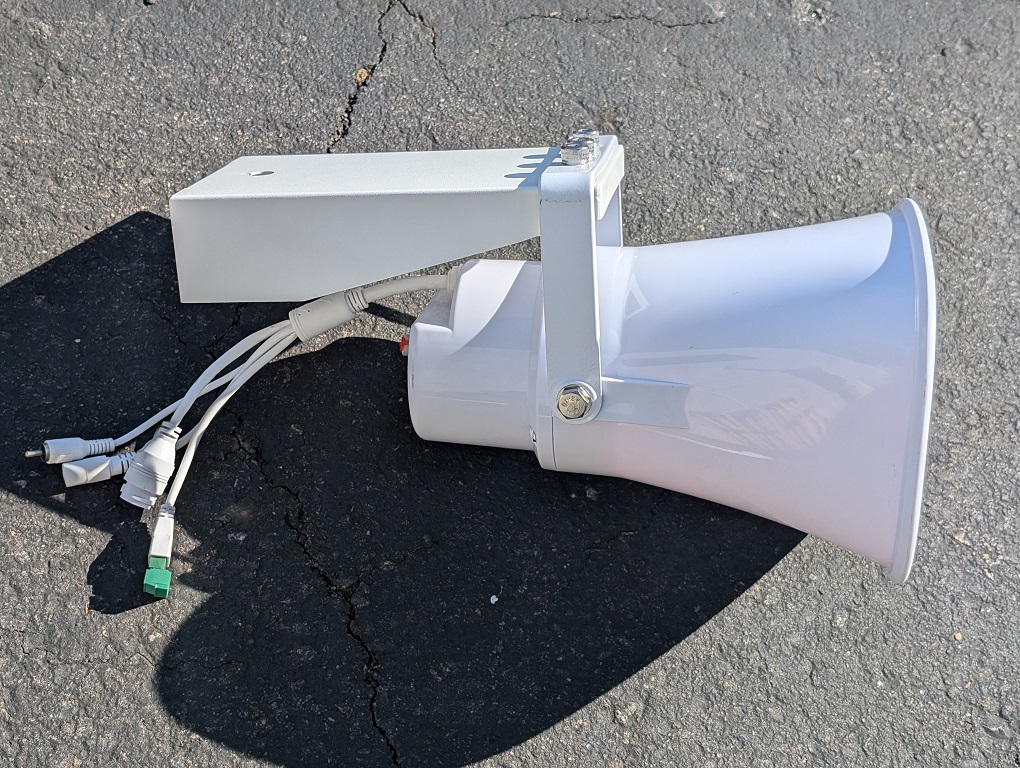
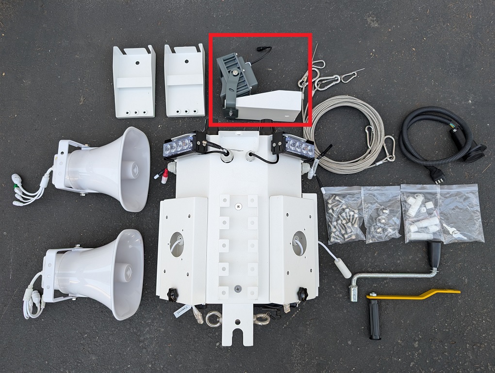
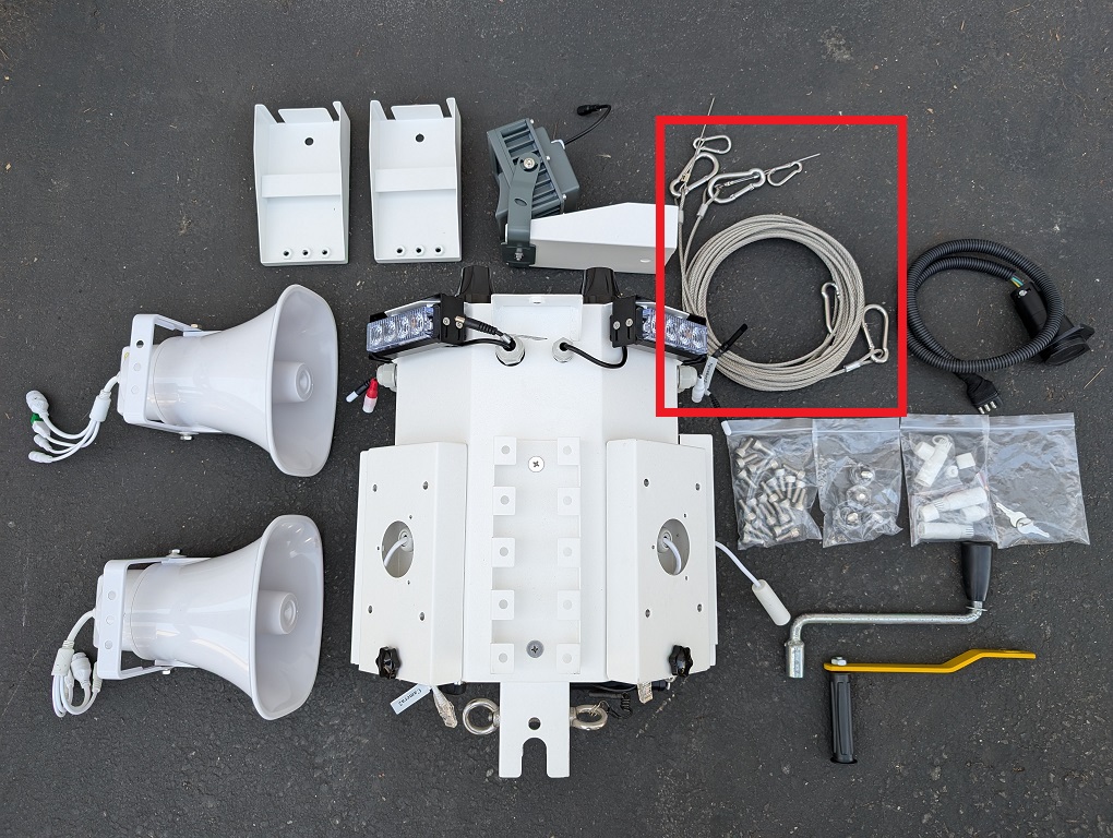
13. Remove all the equipment from the storage box and verify the contents: 1 Control Box, 2 Analog Speakers, 1 Floodlight, 2 Speaker Mounts, 1 Silver Hand Crank, 1 Yellow Hand Crank, 2 Steel Cables, 1 Towing Power Connector, 1 Bag of 2 Small Silver Keys, 1 Bag or 4 Black Plastic Screw Knobs, 1 Bag of 24 Hex Screws, 1 Bag of 4 Sets of Ethernet Waterproofing Connectors.
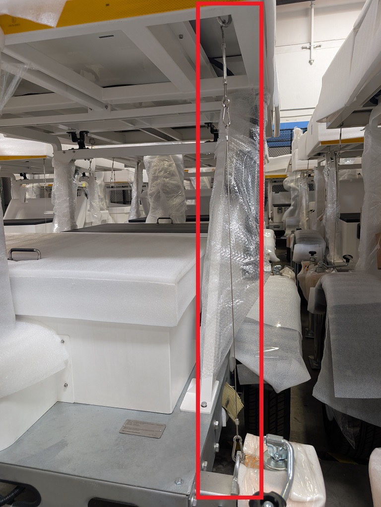
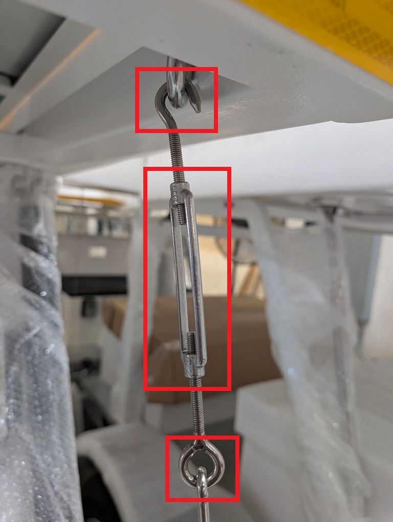
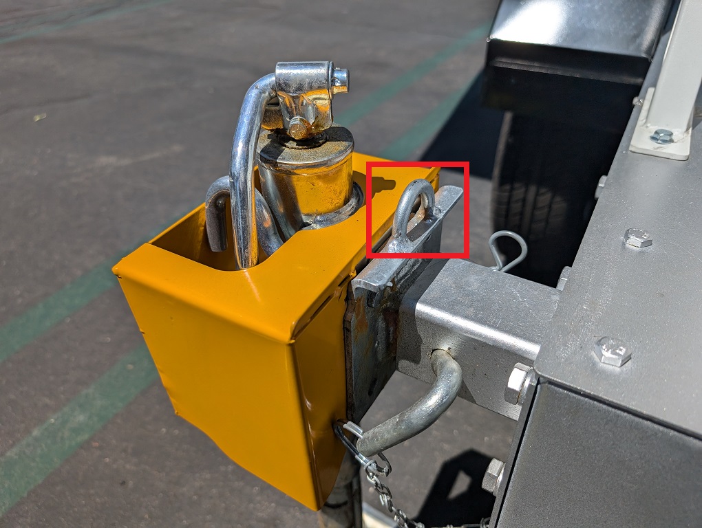
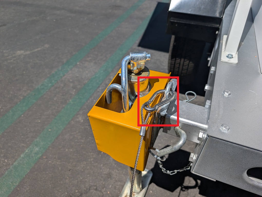
14. Detach one of the stabilizing cables by holding onto the o-ring screw while twisting the rectangular connector counter-clockwise. Remove the hook screw at the top. Then detach the carabiner at the bottom of the cable and stow them in the storage box.
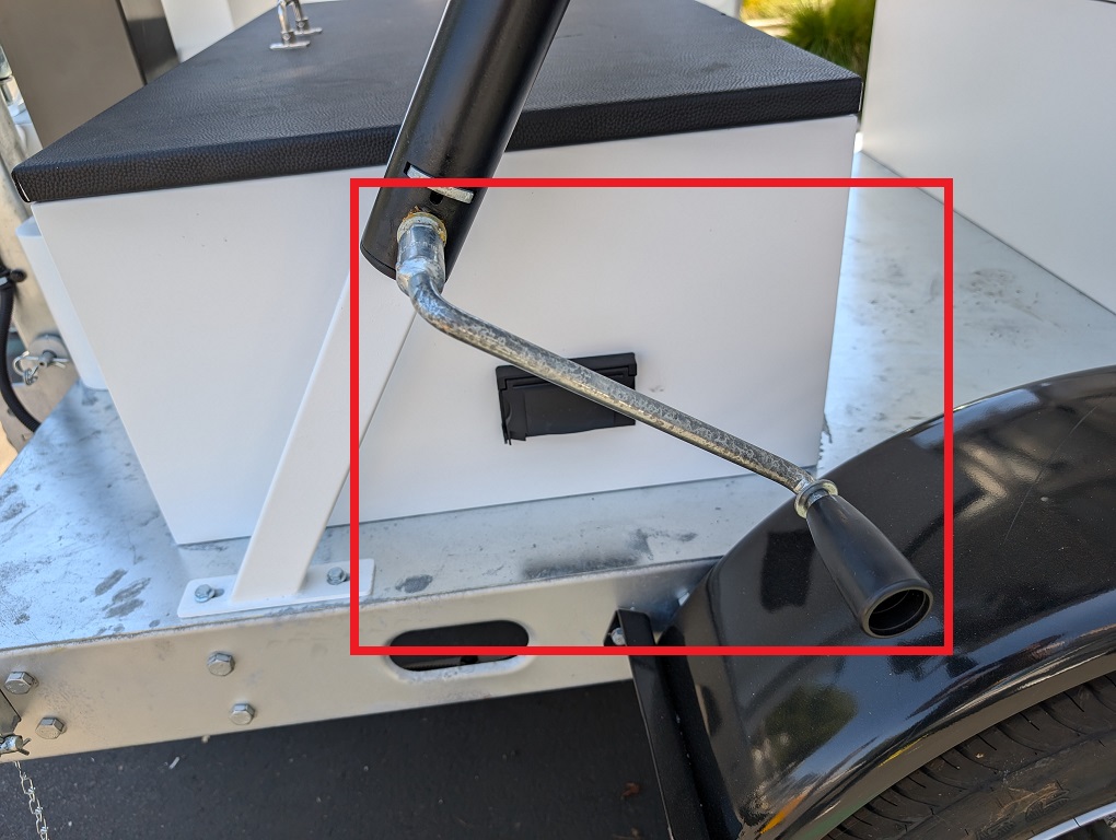
15. Repeat the process for the 3 other stabilizing cables. 16. Locate and retrieve the silver hand crank with the black handle.
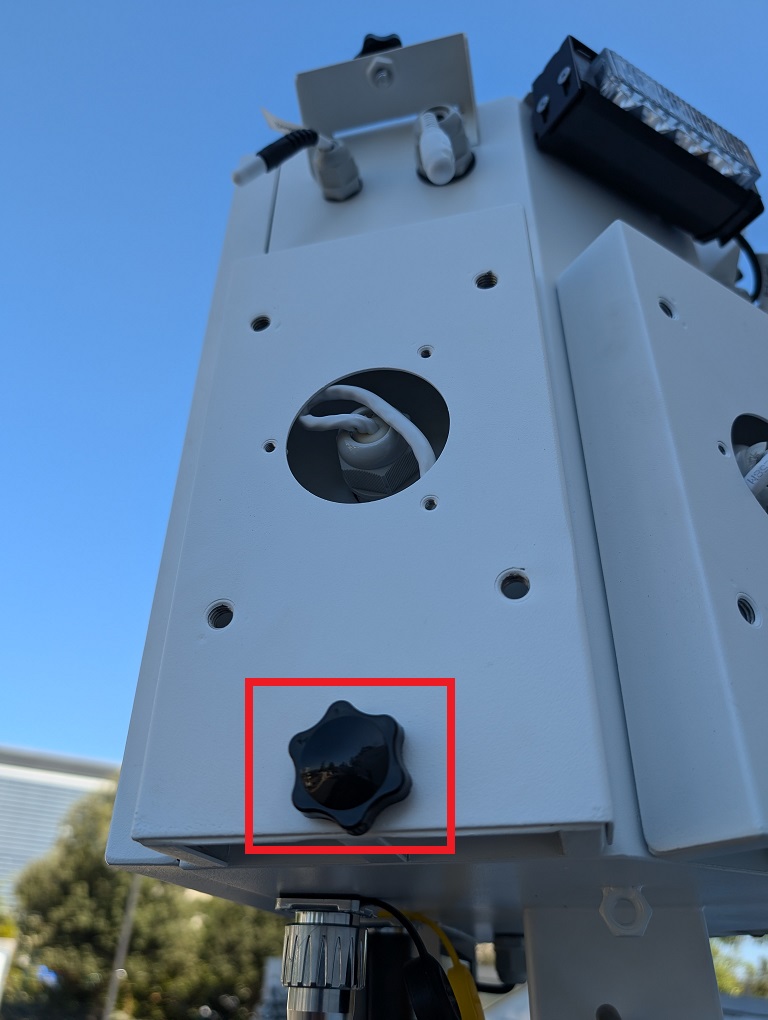
17. Attach the silver hand crank with the black handle to solar panel support and rotate it clockwise to adjust the solar panel. Continue until it’s at the desired angle. Do not raise it past 50 degrees from horizontal.
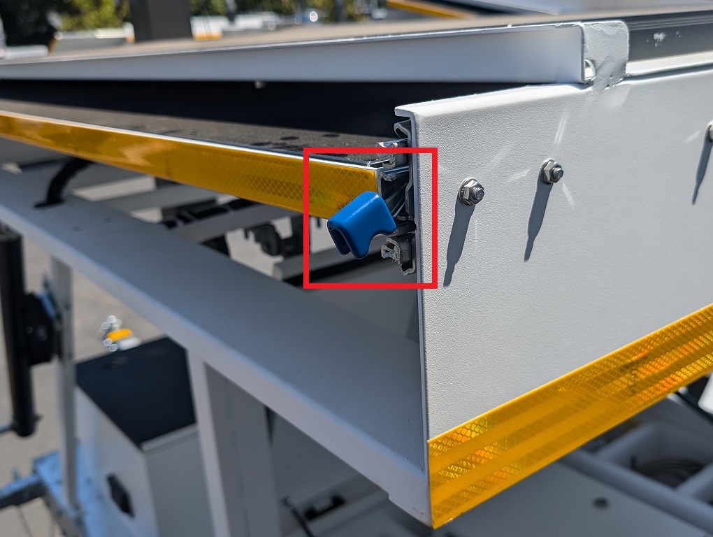
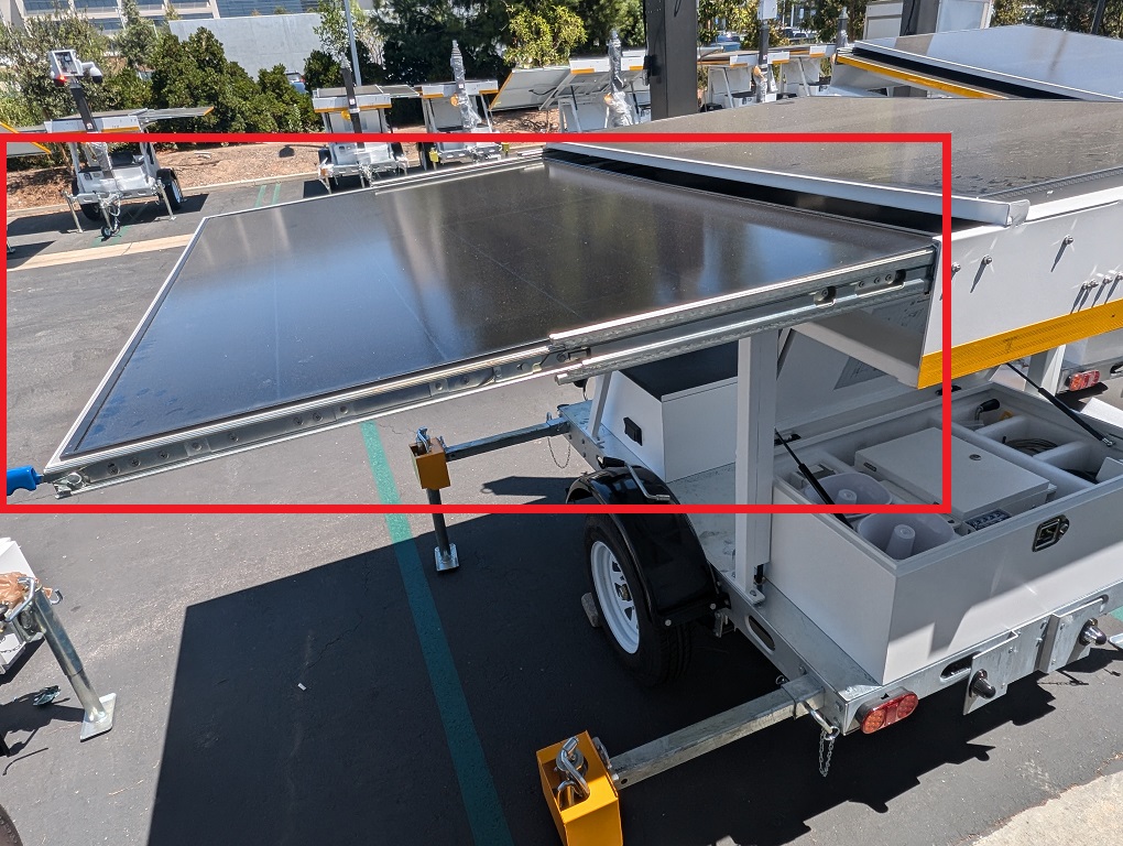
18. Press and hold down on the blue lever at the base of one side of the solar panel. Pull one of the side solar panels outward until it’s fully extended. Repeat on the other side solar panel.
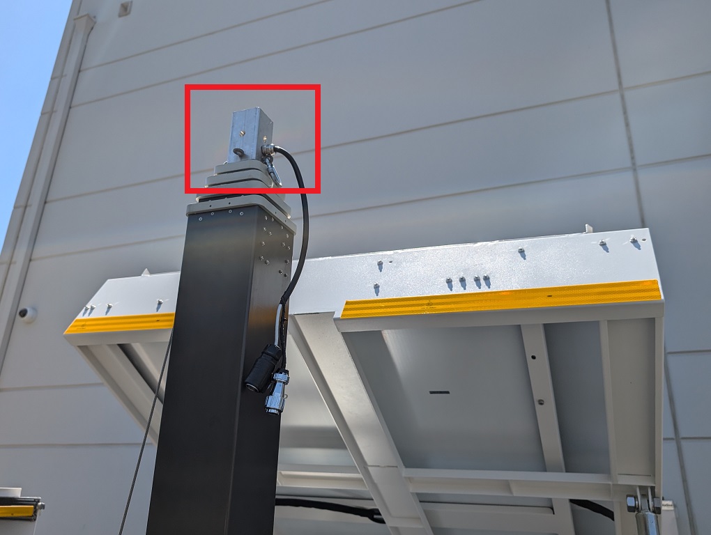
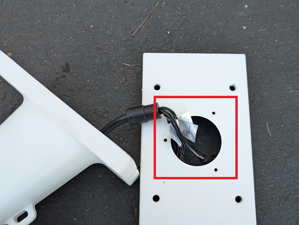
19. Locate and retrieve the control box.
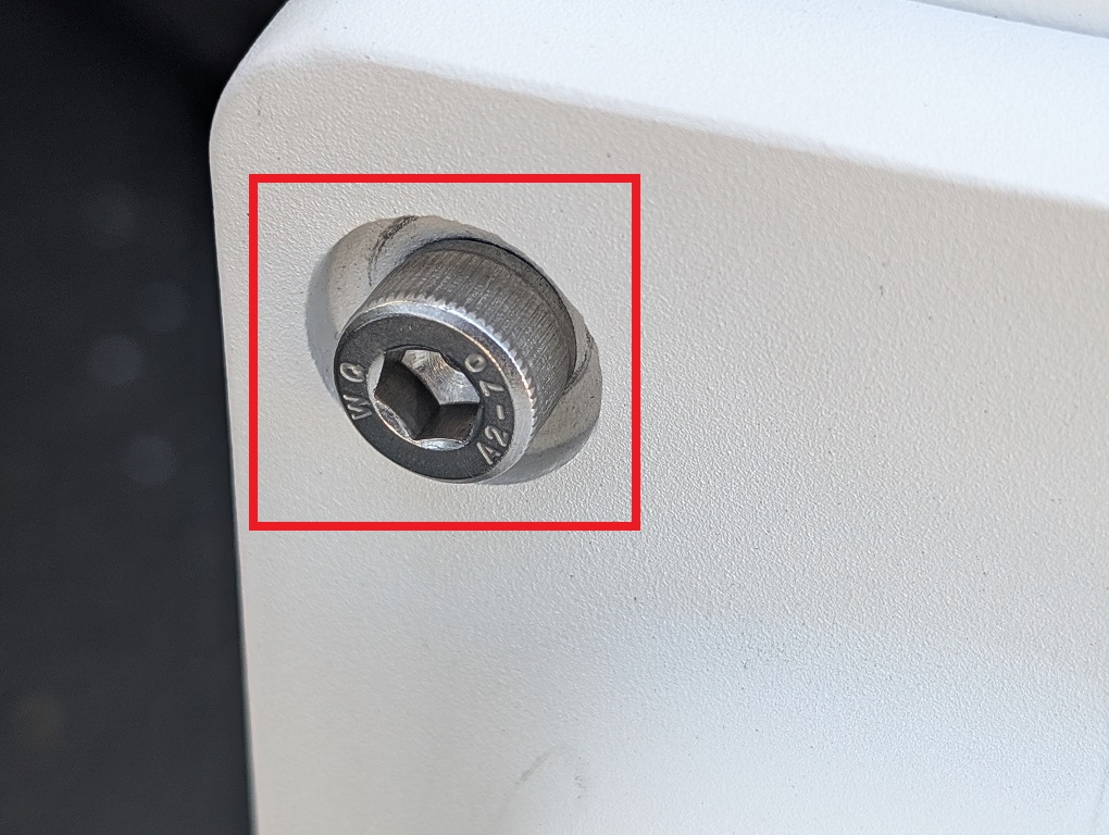
20. Unscrew the O-Nut from the bolt on the base of the control box.
21. Remove the bolt from the base of the control box via the O Ring.
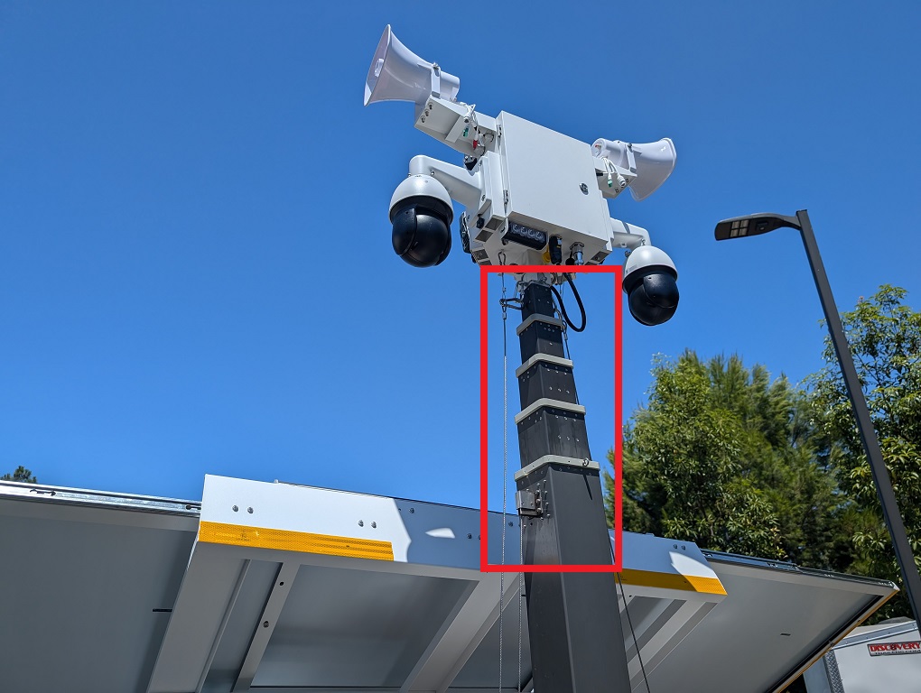
22. Place the base of the Control Box on top of the Mast in whatever direction you prefer.
23. Slide the O Ring Bolt through the holes on both sides of the control box base and mast.
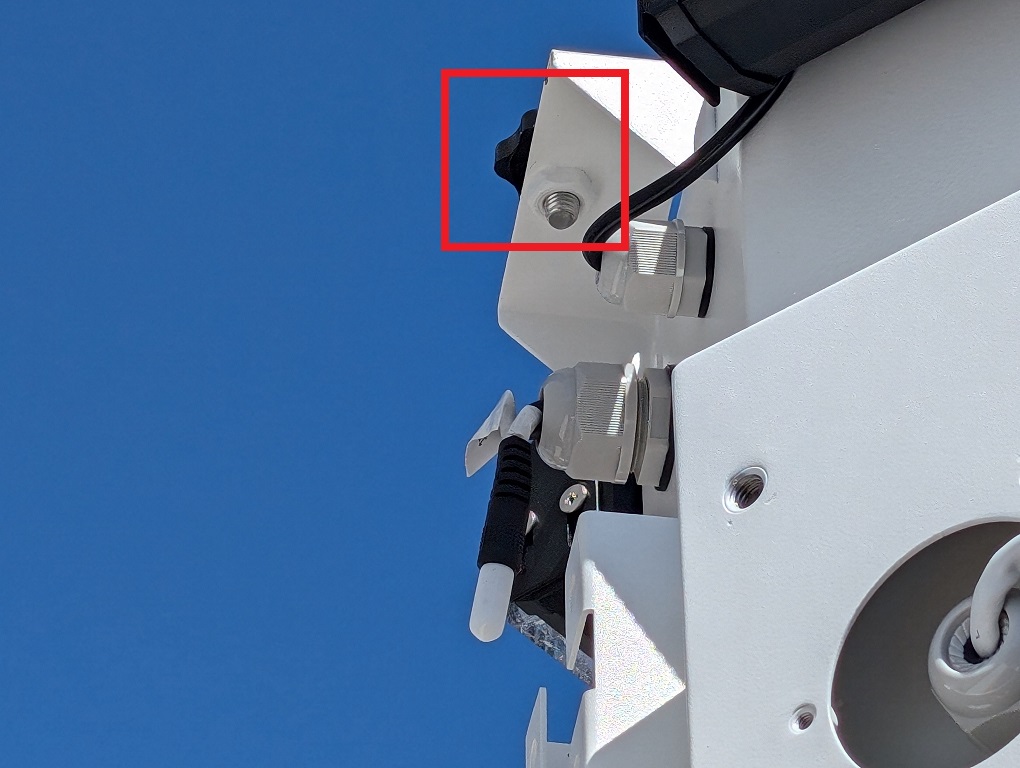
24. Secure the O Ring Bolt with the O Ring Nut.
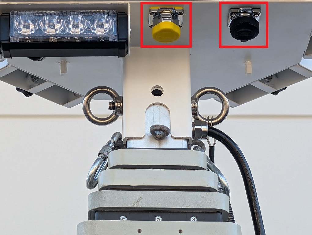
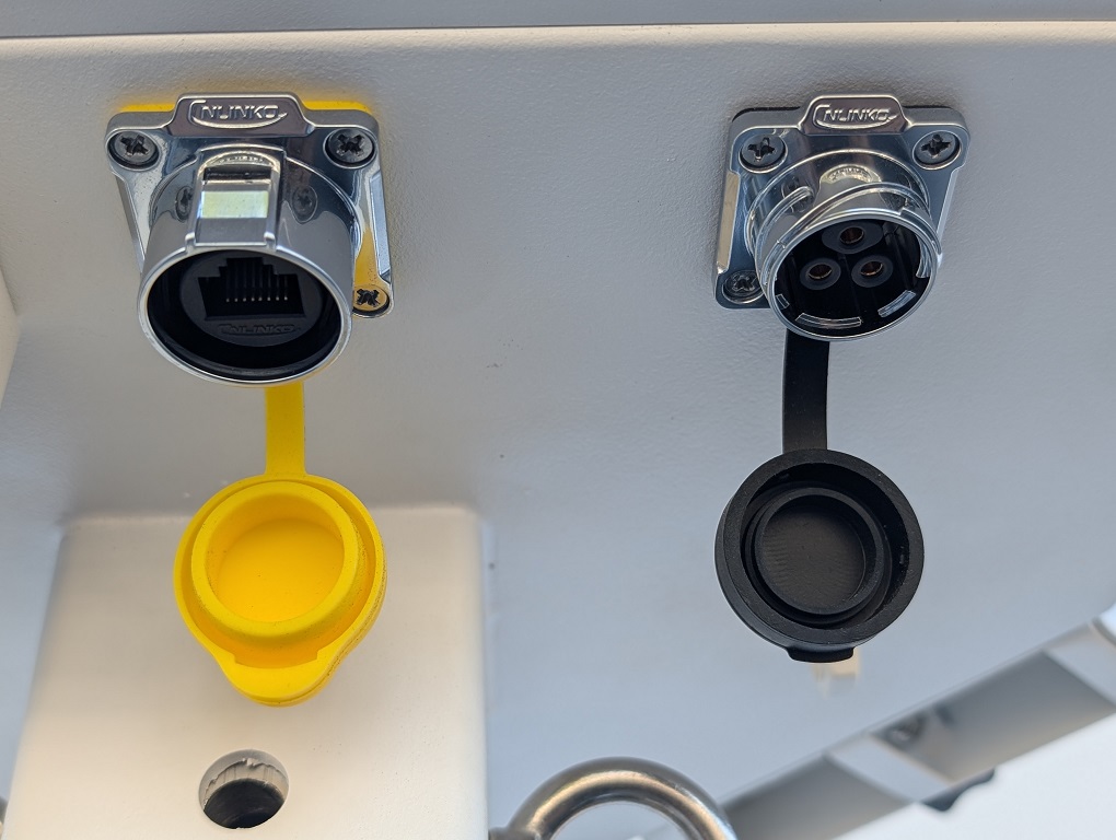
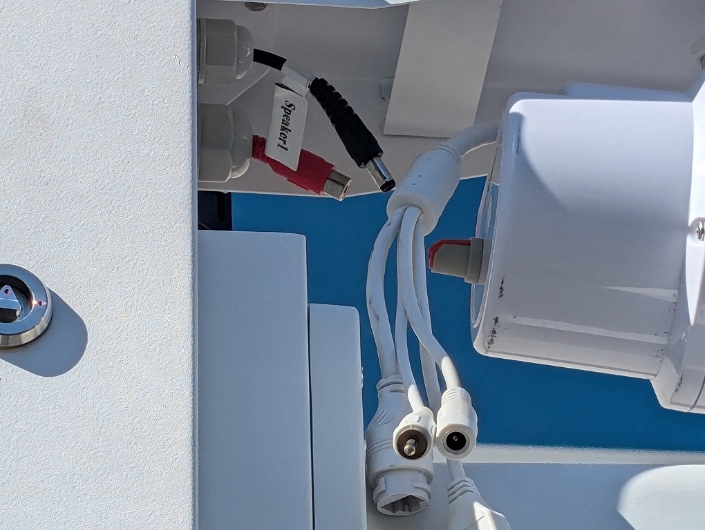
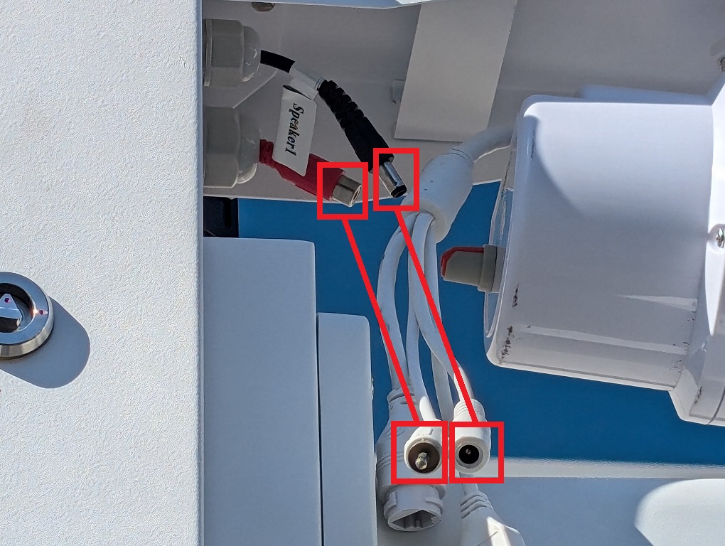
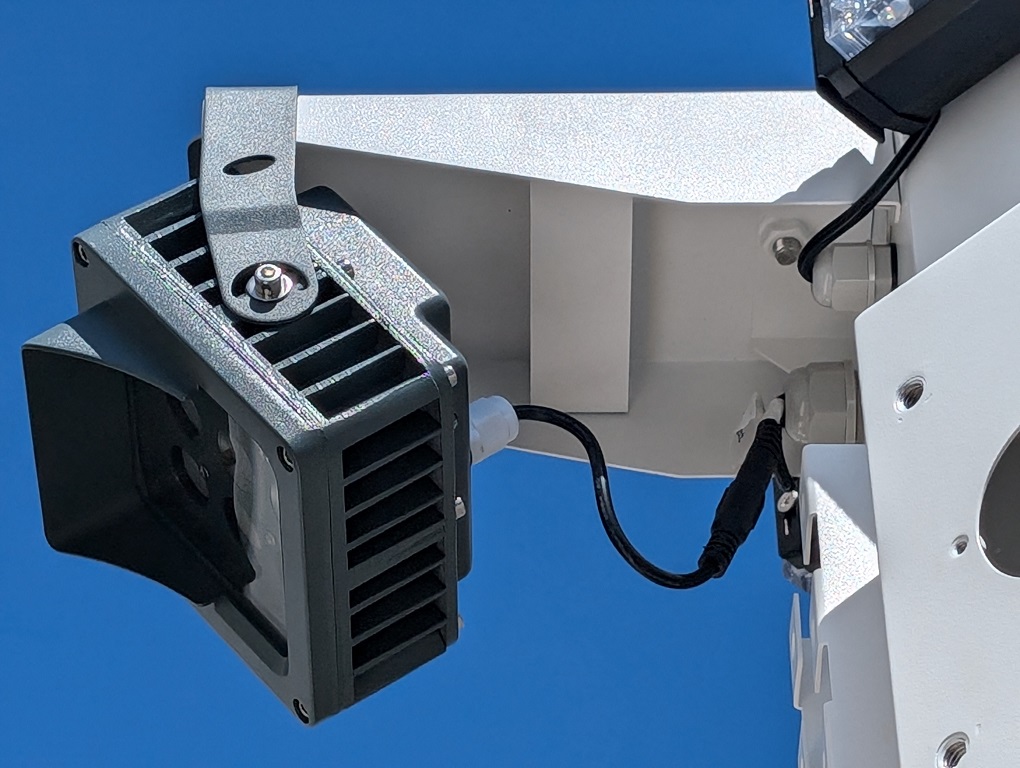
25. Remove the plastic covers of the power ports on the bottom of the Controller Box.
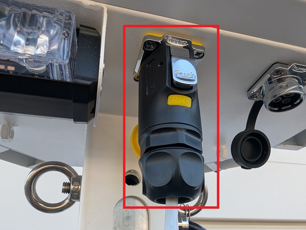
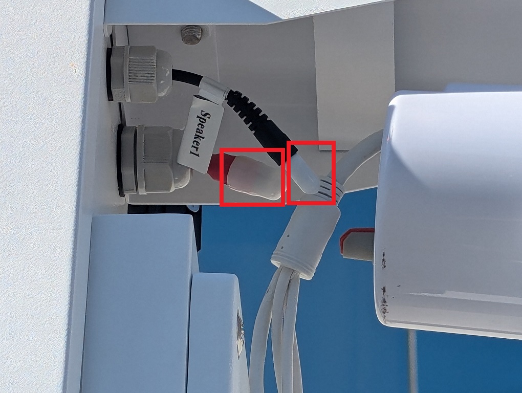
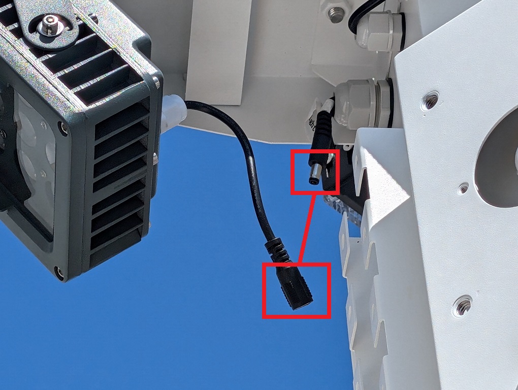
26. Connect the Black power connector, attached to the black power cable on the side of the mast, to the port with the yellow cover. Make sure it locks in place.
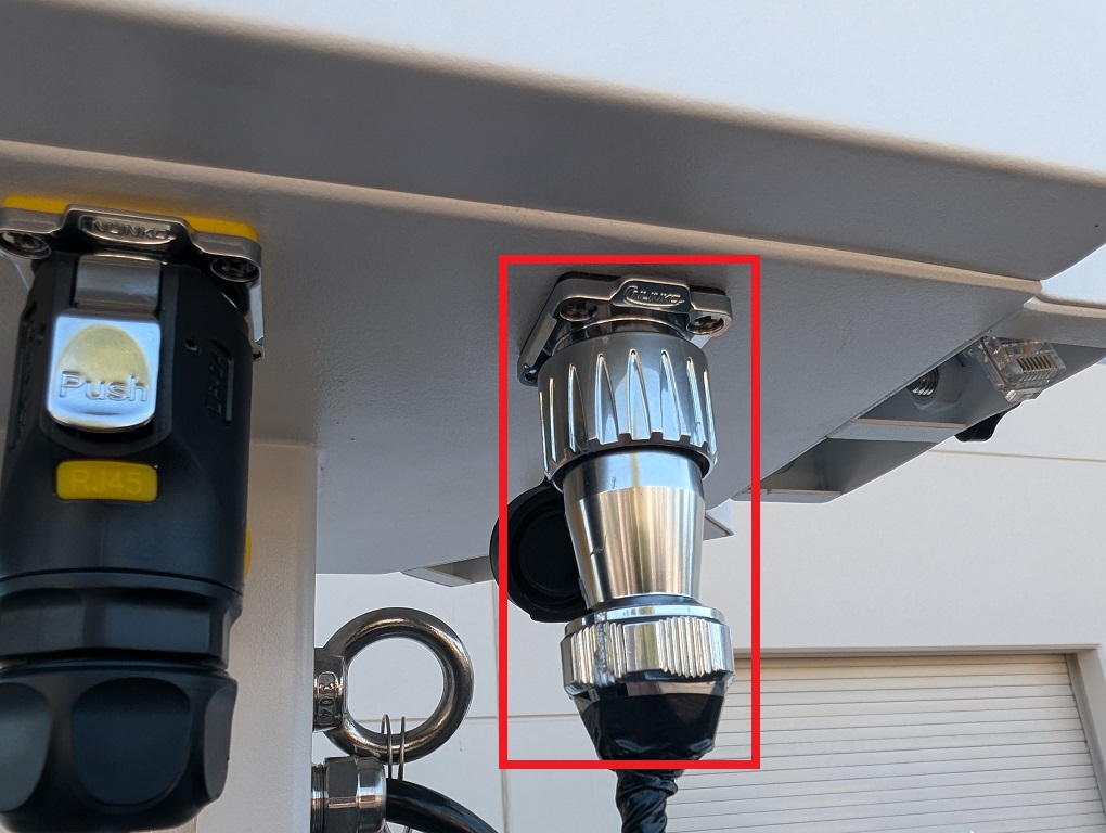
27. Connect the Silver power connector, attached to the black power cable on the side of the mast, to the port with the black cover. Twist the end to lock it in place.
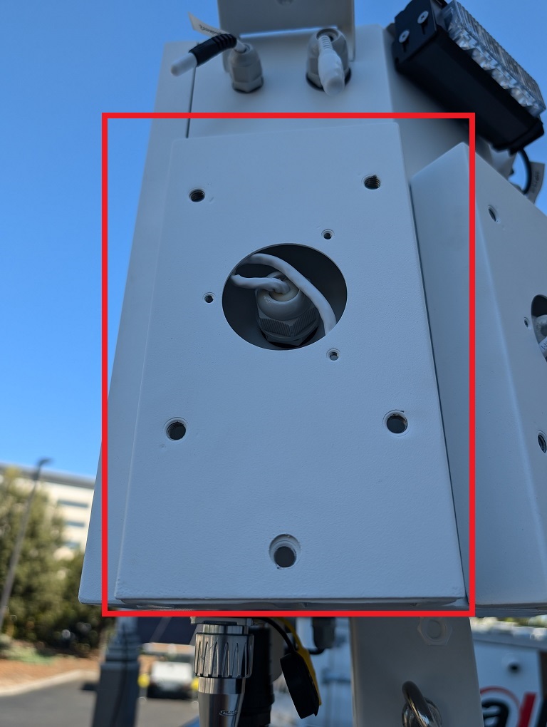
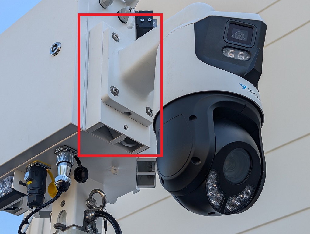
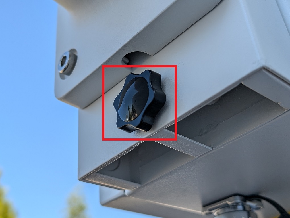
28. Unscrew the black knob screw on one of the camera mounts on the controller box.
29. Push up and then pull out the camera mounting plate to remove it from the controller box.
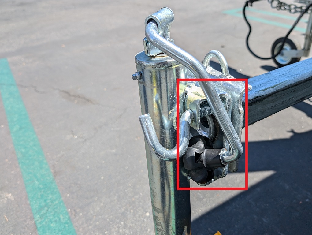
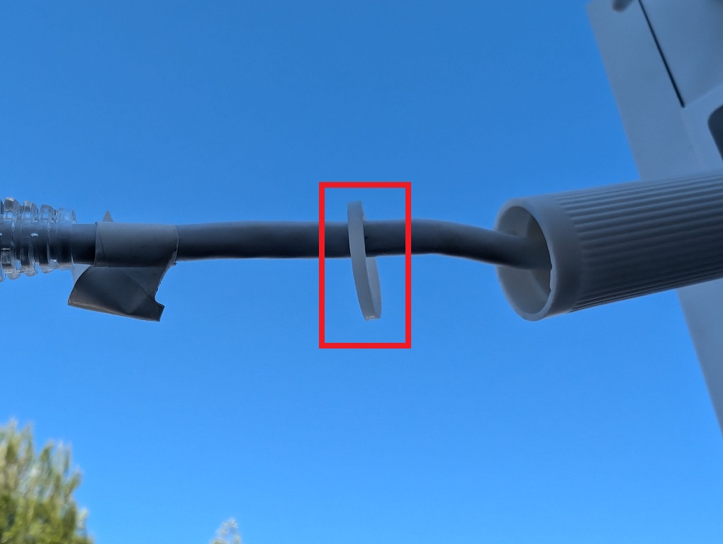
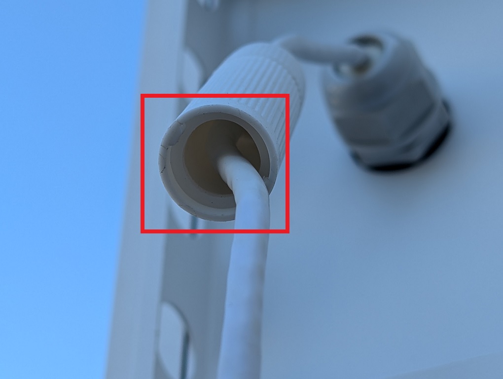
30. Locate and retrieve the bag of Ethernet waterproofing covers.
31. Put the plastic waterproof nut over the ethernet cable on the controller box.
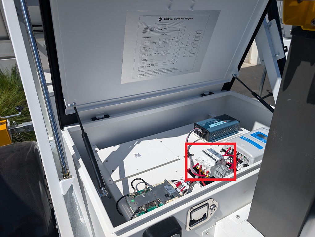
32. Place the rubber waterproof apron over the ethernet cable and slide it into the plastic waterproof nut.
33. Put the plastic waterproof connector over the ethernet cable. Then slide it into the plastic waterproof nut and twist it to lock it in place.
34. Put the rubber O ring over the ethernet cable and slide it into the plastic waterproof connector.
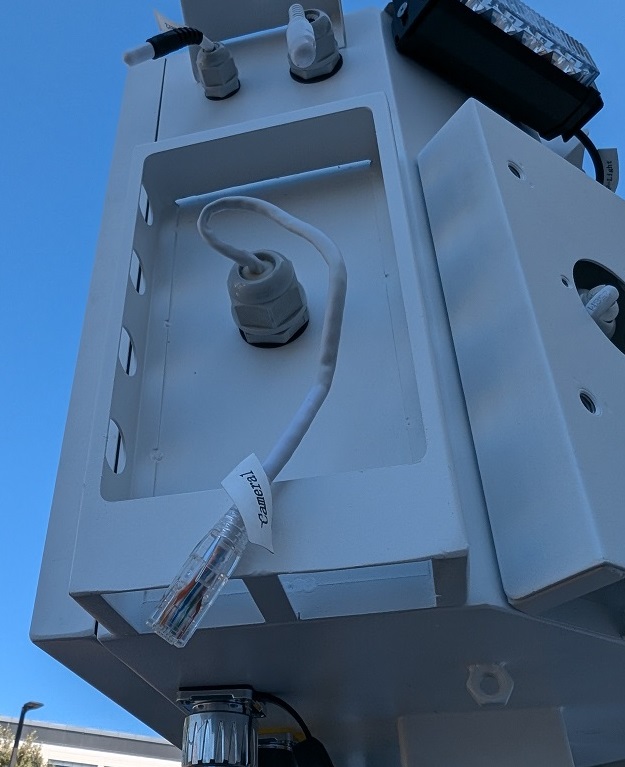
35. Take the camera’s pigtail and side it through the opening in the mounting plate.
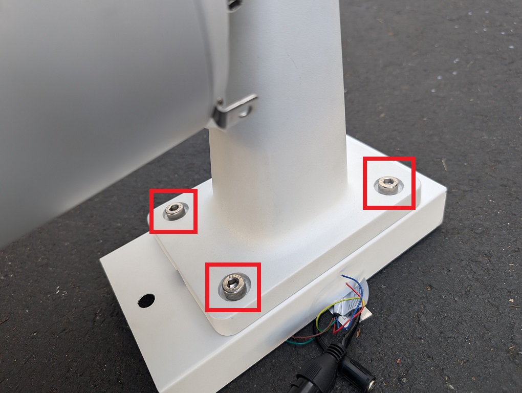
36. Locate and retrieve the bag of hex screws.
37. Put a screw through the hole on the camera’s mount and then through the mounting plate. Screw the hex screw in place. Repeat on the 3 other holes on the camera’s mount and the mounting plate.
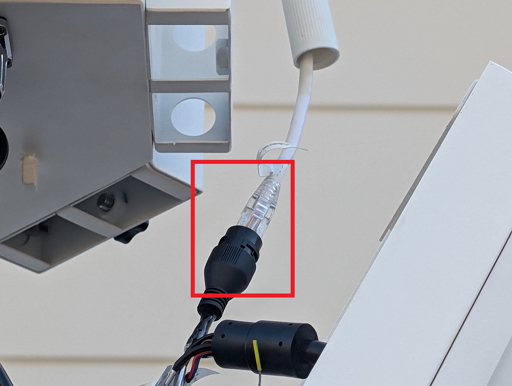
38. Connect the end of the ethernet cable on the control box to the port on the pigtail of the camera. Then push the waterproof connector over the port and twist it to lock it in place.
39. Slide the mounting plate back onto the control box and screw the black knob screw back on to secure it.
40. Repeat the process for up to 3 other cameras. 41. Locate and retrieve one of the analog speakers, one of the speaker mounting plates, and the bag of hex screws.
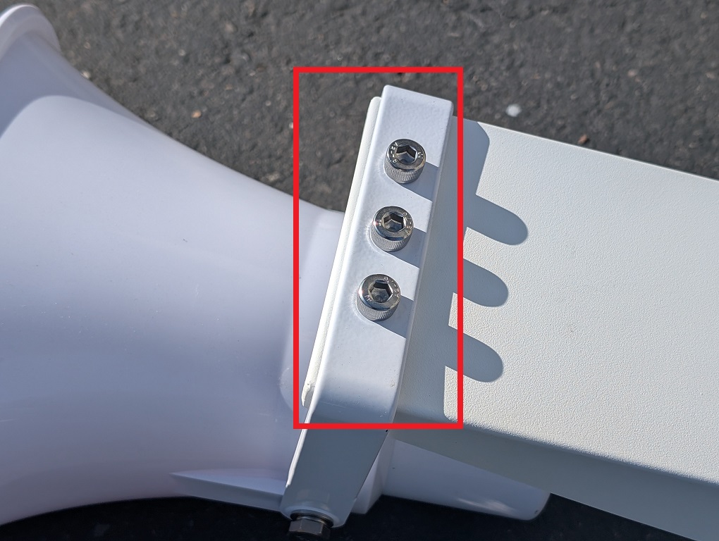
42. Put 3 hex screws through the holes on the speaker’s angle arm and then through the mounting plate. Screw all 3 screws until they are secure.
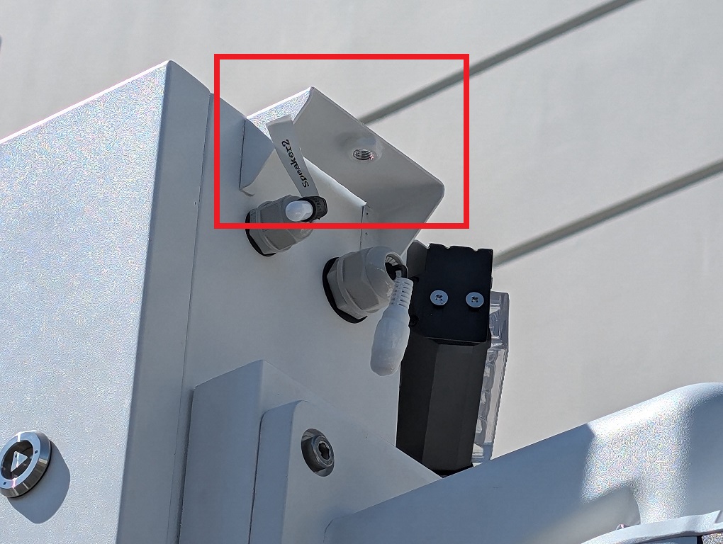
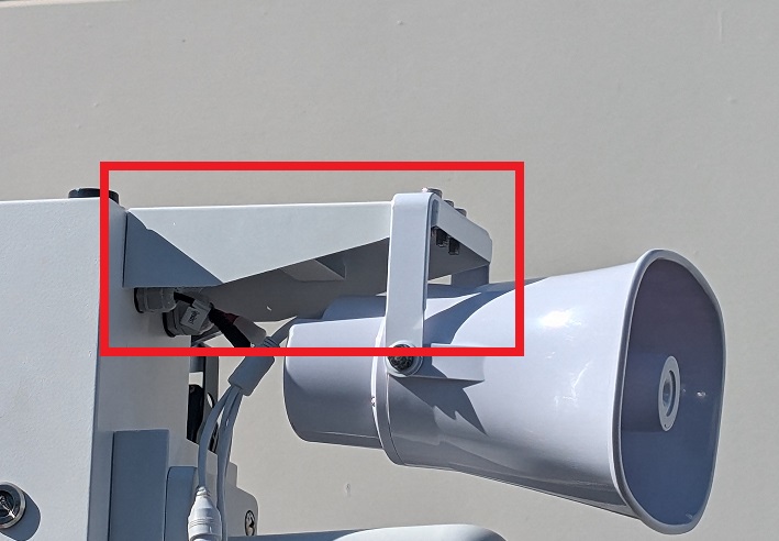
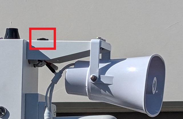
43. Unscrew the black knob screw on one of the speaker mounts on the controller box.
44. Place the speaker mount on the controller box and screw the black knob screw back on to secure it.
45. Remove the covers on the audio and power connectors on the controller box.
46. Plug the audio input cable of the speaker into the audio output port on the controller box. Plug the power cable on the speaker into the power connector on the controller box.
47. Repeat the process for the other speaker. 48. Unscrew the black knob screw on the flood light mount on the controller box.
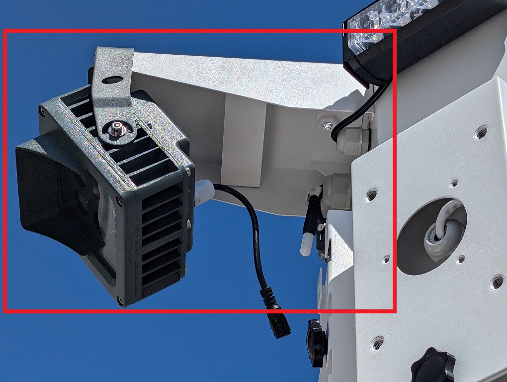
49. Locate and retrieve the pre-mounted floodlight.
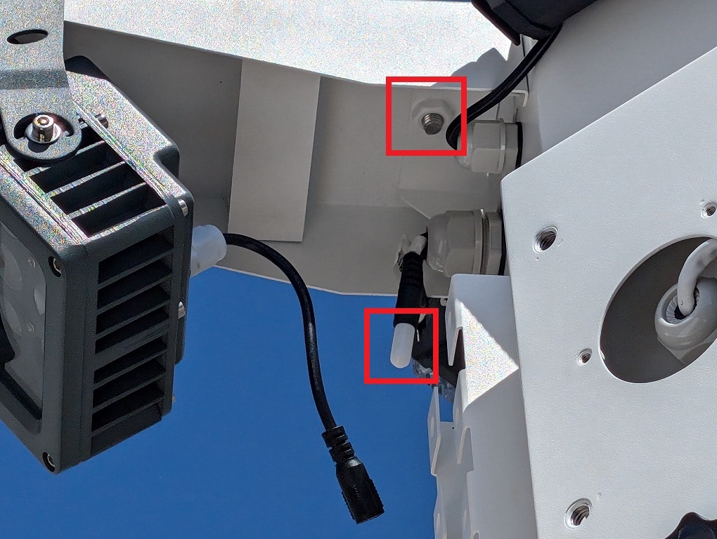
50. Place the floodlight on the controller box. Then screw the black knob screw back onto the controller box to secure the floodlight. Remove the cover on the power connector on the controller box.
51. Plug the power cable on the floodlight into the power connector on the controller box.
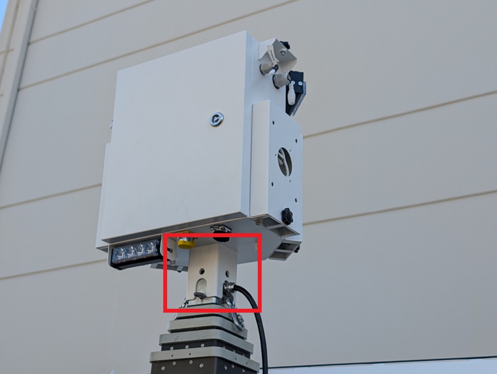
52. Locate and retrieve the steel cables.
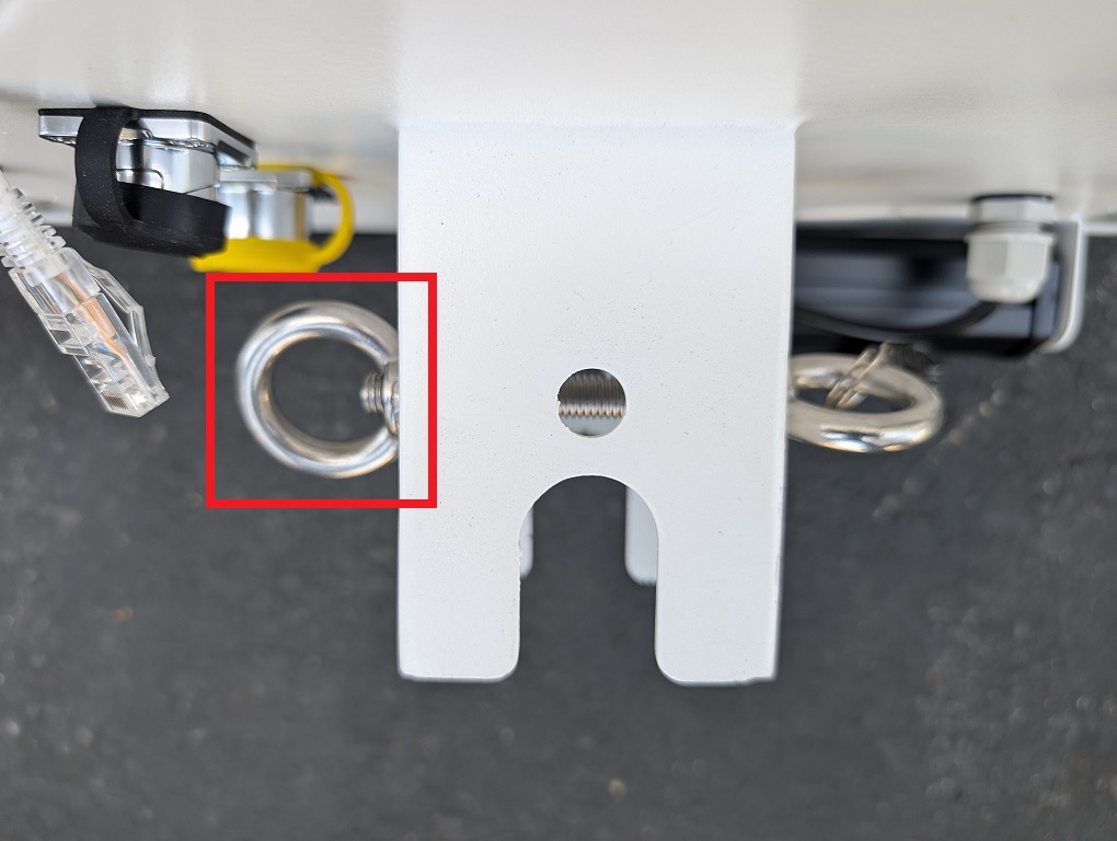
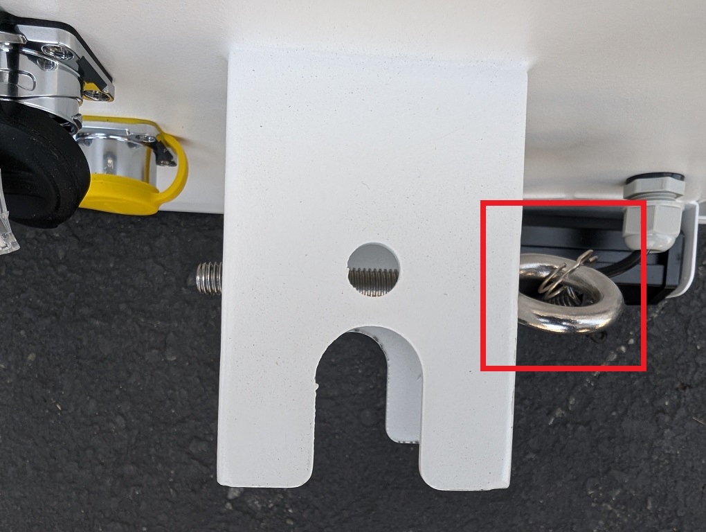
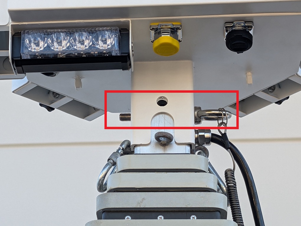
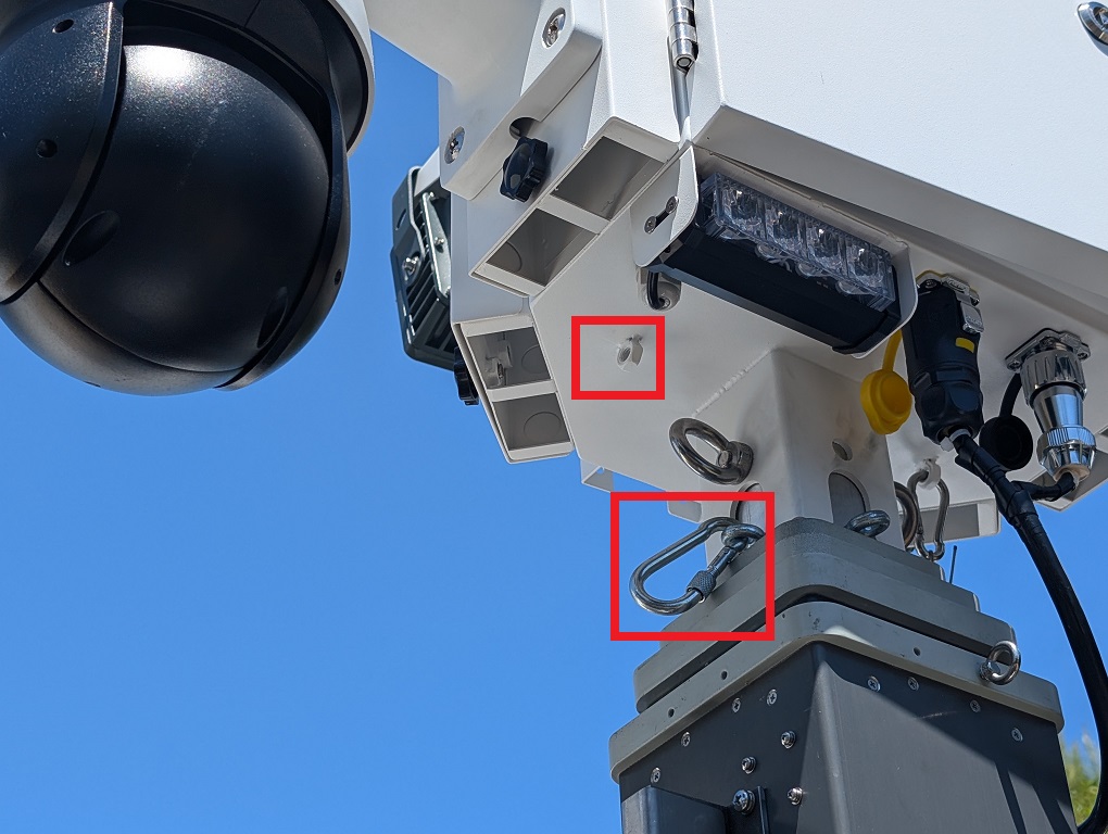
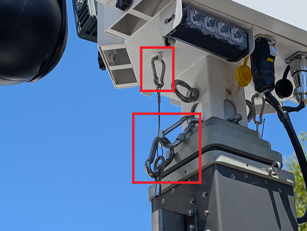
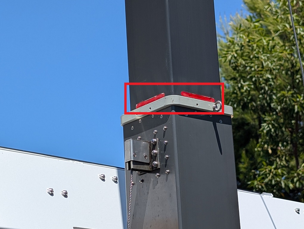
53. Unspool the steel cables. Then connect the single carabiner on one end of one of the cables to one of the supports on the side of the LumiGuardian trailer nearest to the control box.
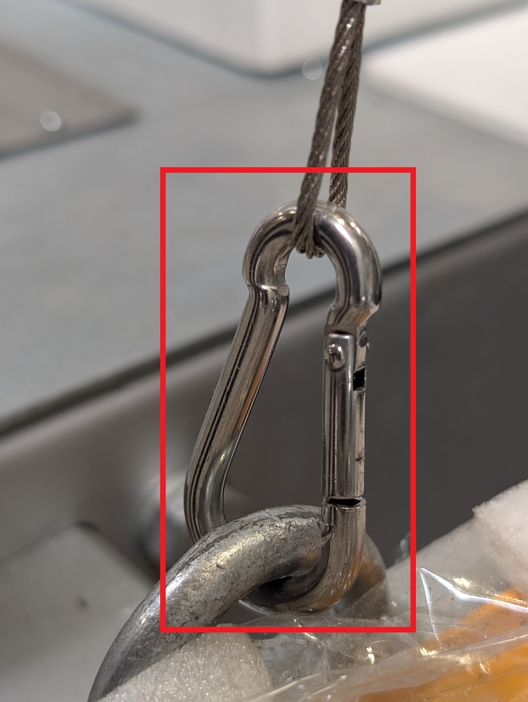
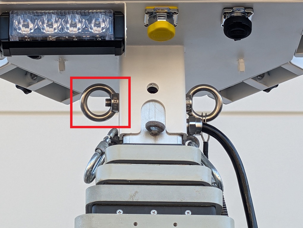
54. Connect one of the two carabiners on the other end of the steel cable to the carabiner on the mast closest to the support, and the other carabiner to the bottom of the control box.
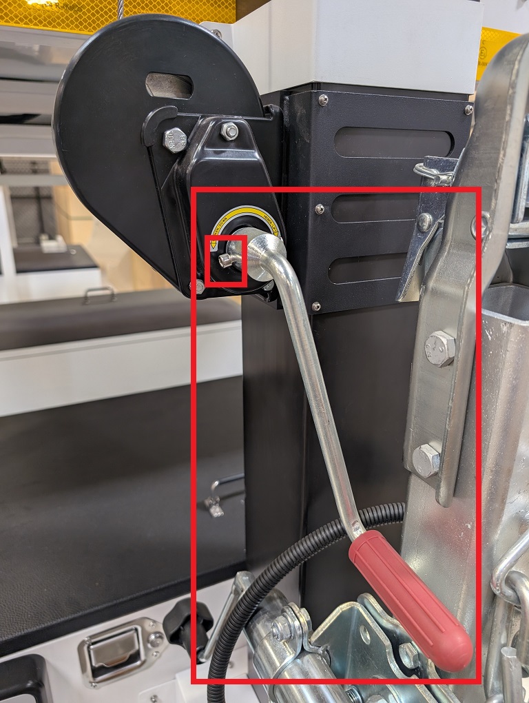
55. Repeat this process for the other support on the other side of the control box. 56. Locate and retrieve the silver hand crank with the red handle. Place it on the crank connector on the mast, ensuring it fits properly on the silver metal connector. Tighten the hex screw built into the crank handle to secure it.
57. Crank the silver hand crank with the red handle clockwise to raise the mast. Stop when the red line appears on the mast. Do not crank past that point.
58. Use the small silver key from the lockbox to unlock the electrical box. Pull and hold the metal handle outward with one hand, while using the other hand to lift the plastic black handle upward to open the electrical box. Then locate the power switches.
59. Set the Power Mode via the Power Switches:
Note: Make sure to turn the switches on in order from left to right. Also, do not constantly turn the switches on and off; it could cause damage to the circuit breakers. Close the cover to the electrical box. 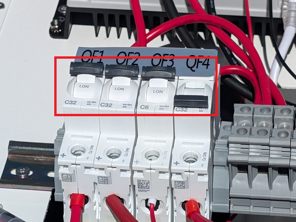 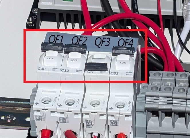
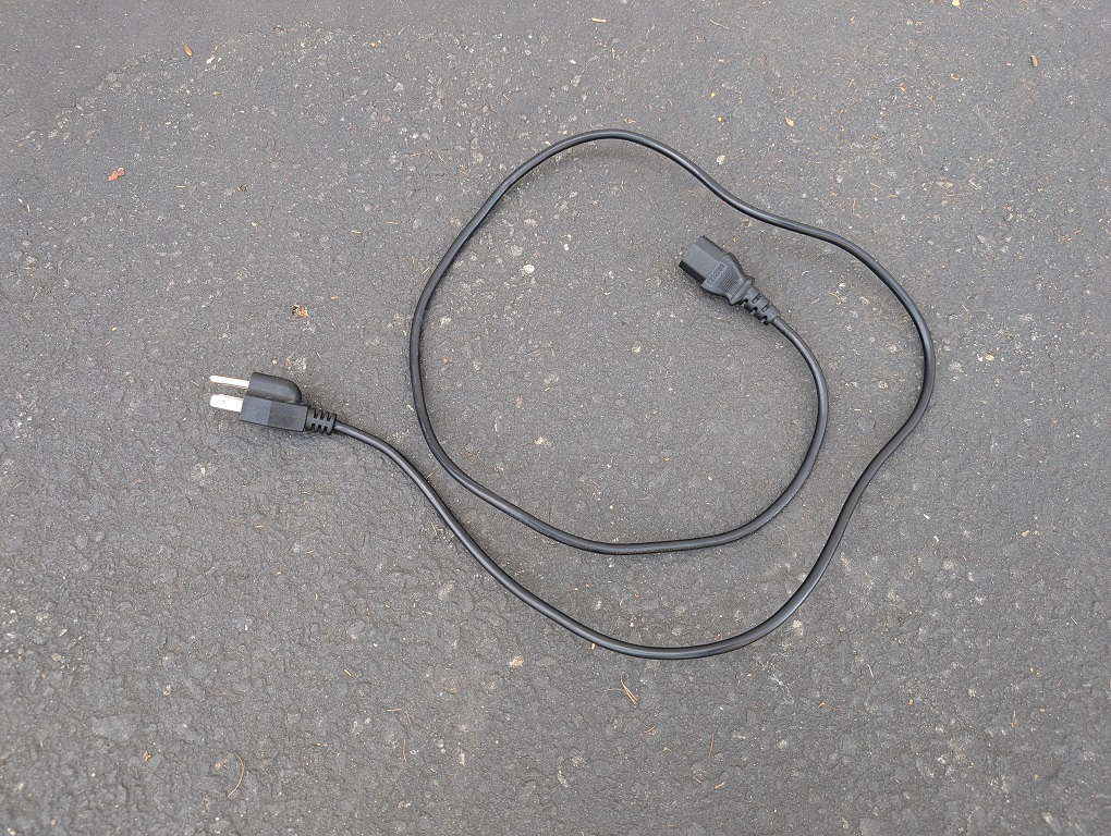
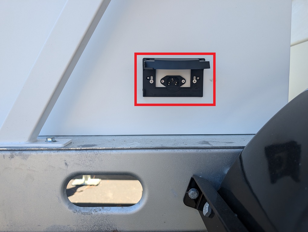
Optional: Charging Mode via Power CableNote: Charging via power cable should only be performed if there is little to no light available to charge via the solar panels. LumiGuardian will prioritize charging via only one power source (Solar Panel or Power Cable) based on whichever is inputting more wattage into the system. When there is enough light available, LumiGuardian will charge faster via solar panel. 1. Using a C13 power cable (not included) you can charge the LumiGuardian trailer via power from a wall plug.
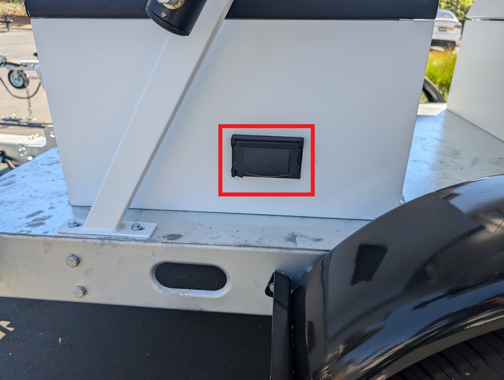
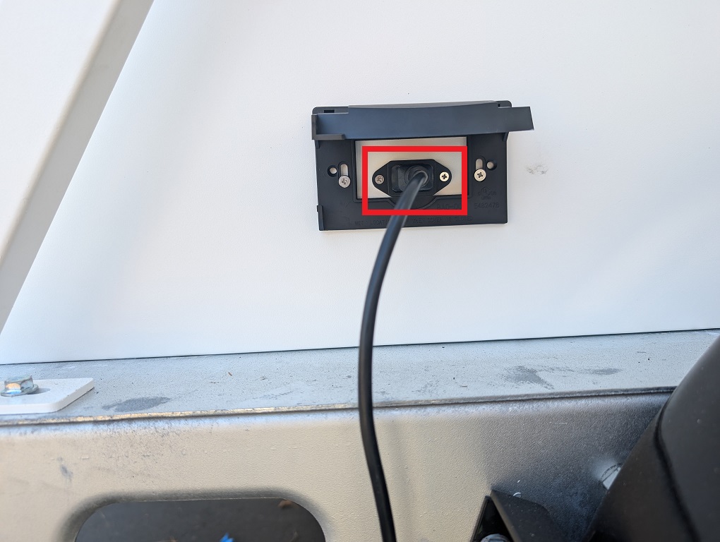
2. Open the cover on the power port on the side of the electrical box.
3. Connect the power cable to the power port and then plug it into a wall socket or surge protector.
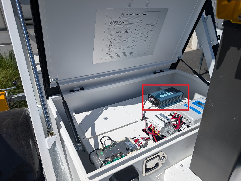
4. Use the small silver key from the lockbox to unlock the electrical box. Pull on the handle to open the electrical box. Then locate the power supply box.
5. Turn the AC Input switch to the On position.
6. Locate the power switches
7. Turn on switches QF1, QF2, and QF4; keep QF3 in the off position. Note: Make sure to turn the switches on in order from left to right. Also, do not constantly turn the switches on and off; it could cause damage to the circuit breakers. Close the cover to the electrical box.
 Back to Top Part 2: LumiCloud User Account Creation via Partner PortalStep by Step Instructions1. Open a web browser and navigate to the LumiCloud Partner Portal.
2. Click on Customer on the left to expand it.
3. Click on Add on the right
4. Click on the drop down under Region/Country, then select the country that the user is located in.
5. You will see the newly added user at the top of the list.
6. A new tab will be opened in your web browser with the LumiCloud User Portal, and you will be automatically logged into the user's account.
7. You will be brought to the Enterprise tab of the Settings page.
8. Enter the name of the Organization or Company in the Organization Name field.
Click on Save at the bottom
9. Click on Confirm
10. When you are done making changes to the user's account, click on Complete Installation at the top
11. Enter the user's email in the Confirm Email field
Back to Top Part 3: LumiCloud User Account SetupStep by Step Instructions1. Open the email you recieved after your LumiCloud Managing Partner created your account.
2. The LumiCloud User Portal will open up in your web browser and you will be presented with the Account Activation page.
3. Enter your email address associated with your LumiCloud User Account in the User Account field.
4. Read and scroll through the Service Agreement.
5. Read and scroll through the Privacy Policy.
6. You will be logged into your account on the Dashboard page.
Back to Top Part 4: Adding LumiGuardian Devices to a LumiCloud User Account via Partner PortalStep by Step Instructions1. Open a web browser and log in to the LumiCloud Partner Portal.
2. Select either 1 hour, 4 hours, or 24 hours for the amount of time your partner account will have access to the user's account.
3. The user who owns the account will need to log into their account in a web browser.
4. Back in the LumiCloud Partner Portal, in the Customer Management section, the Obtain Authorization option should change to a Link option.
5. You will be automatically logged into the user's account.
6. Click on Solar Device on the left.
7. Enter the Serial Number of the LumiGuardian device you want to add to this user account in the Device SN field.
8. Enter the password of the LumiGuardian device in the Password field. If the device has not been intialized, you will be creating the password here.
9. Check the Enable box next to DST if the region the LumiGuardian device is located in observes Daylight Savings Time.
10. The settings will be saved and it will say Successful Added.
11. The newly added LumiGuardian device will now be in the device list and will have a Green circle to show it is online
Back to Top Part 5: LumiGuardian - Allocate Licenses in the Partner PortalVideo Instructions
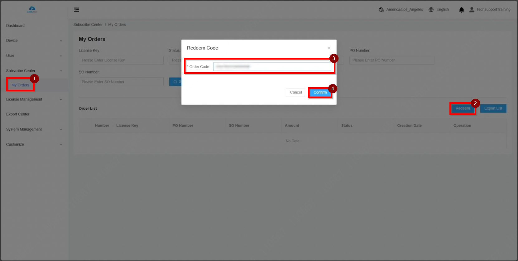
Step by Step Instructions1. After receiving the license key, log in to the partner portal and navigate to "My Orders." Select "Redeem," enter the license key, and click "Confirm."
2. Once redeemed, the license appears under the "Order List."
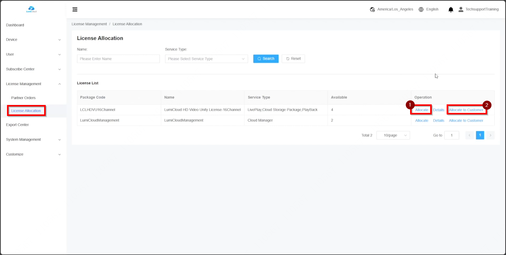
3. To allocate licenses, go to "License Allocation." Licenses can be assigned in two ways: dealers can apply the license directly to a device, or the license can be assigned to an end user for application.
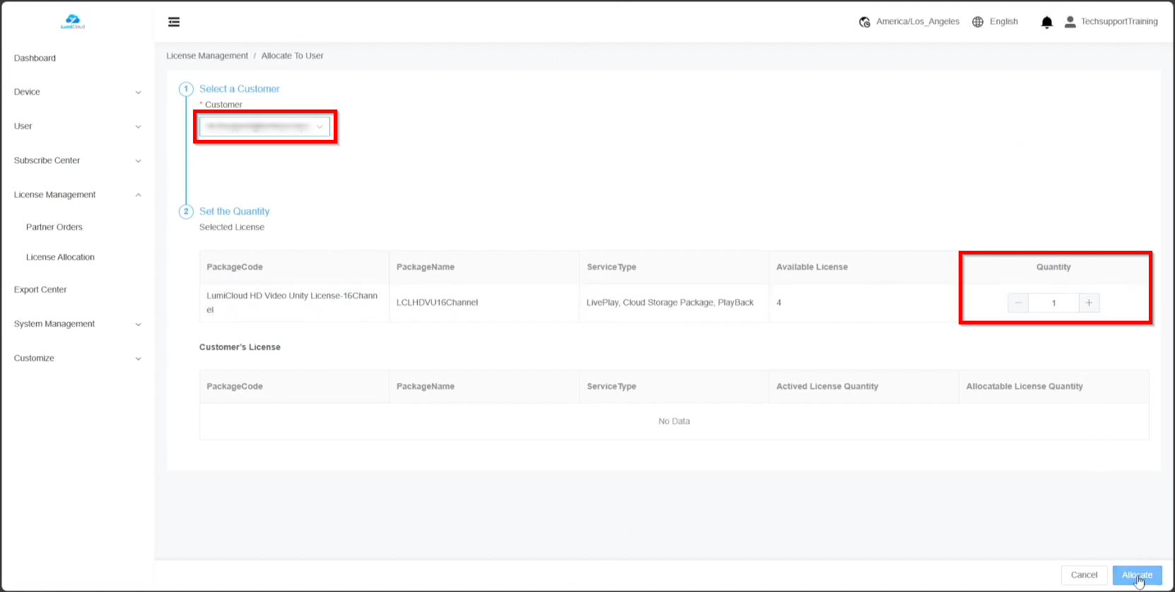
The first method involves assigning the license to an end user. Select the user from the drop-down list, adjust the license quantity, and click "Allocate."
The available license count updates accordingly, reflecting the deducted amount.
The second method involves dealers applying the license directly to a device.
4. To verify license application, select "Details."
|