LumiGuardian/LumiGuardian Starlink setup: Difference between revisions
Techsupport (talk | contribs) |
Techsupport (talk | contribs) No edit summary |
||
| Line 47: | Line 47: | ||
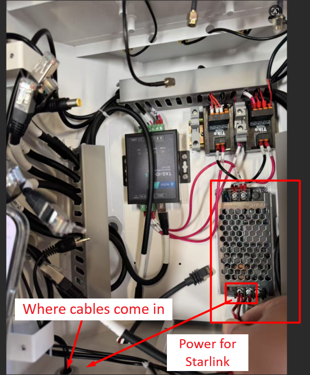
9. Use a voltmeter to identify the correct 48 VDC polarity for the Starlink power connection. | 9. Use a voltmeter to identify the correct 48 VDC polarity for the Starlink power connection. | ||
[[File:LumiGuardian_Starlink_9. | [[File:LumiGuardian_Starlink_9.png|512px|link=https://wiki.luminyscorp.com/images/6/6d/LumiGuardian_Starlink_9.png]] | ||
Revision as of 15:41, 27 October 2026
☰ Navigation Menu ▾

Starlink setup for LumiGuardian
Description
For Internal Use Only: A brief introduction to the idea of using Starlink for LumiWatch deployments.
Prerequisites
- Any tool necessary for installation.
Step by step
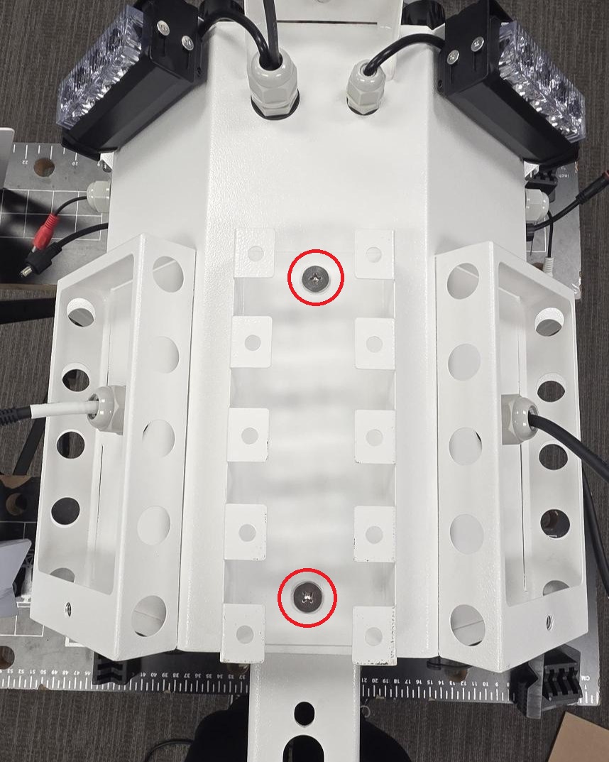
1. Remove the two screws securing the bracket to the control box, then remove the bracket.
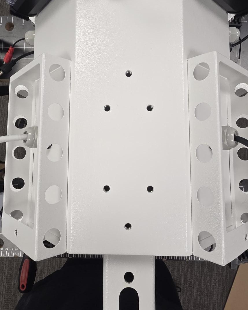
2. Align the four holes on the mounting arm with the four threaded holes exposed after removing the bracket, then secure the mounting arm using the four screws.
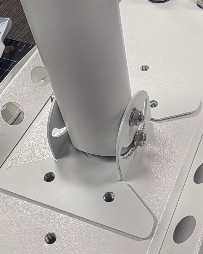
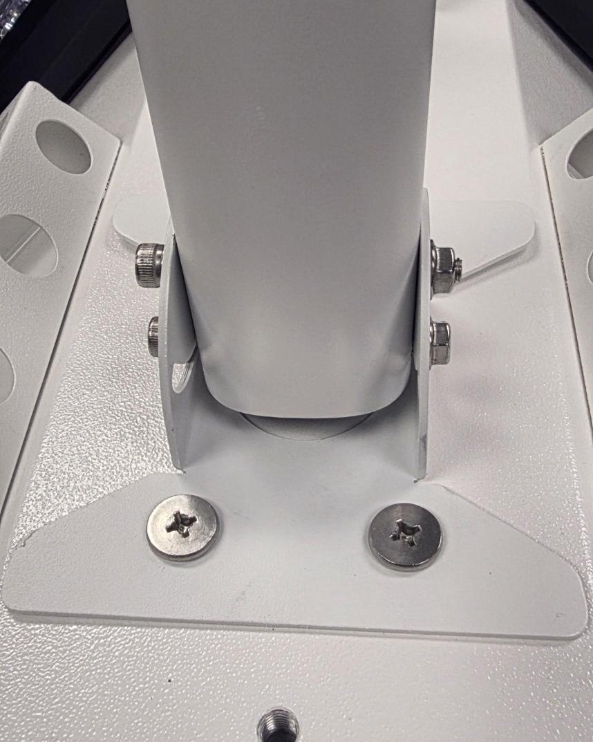
3. From the bottom of the mounting arm, feed the power cable (plug end first) and the Ethernet cable through the arm.
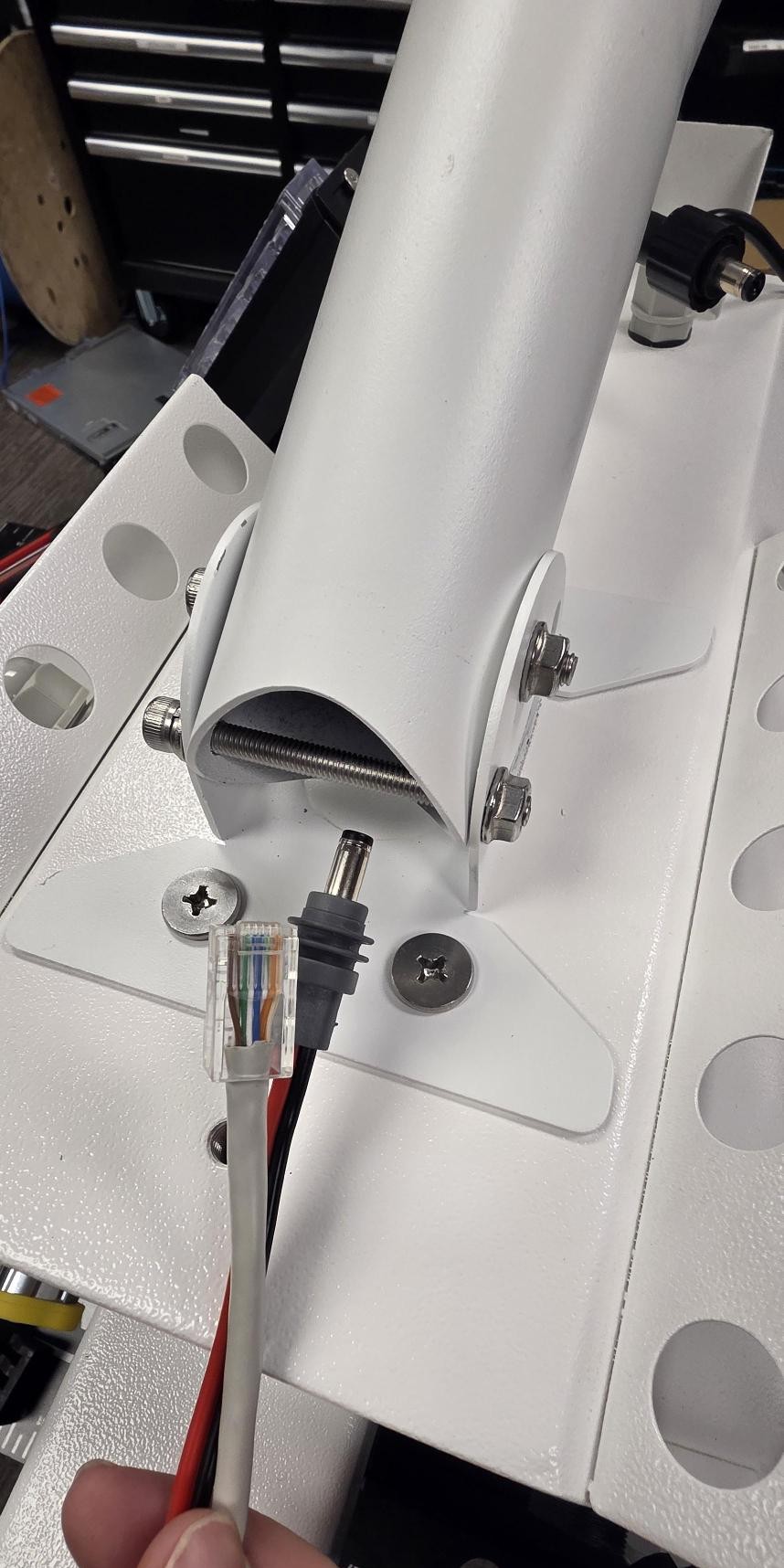
4. From the top of the mounting arm, where the cables exit, feed the cables through the opening in the Starlink mounting bracket.
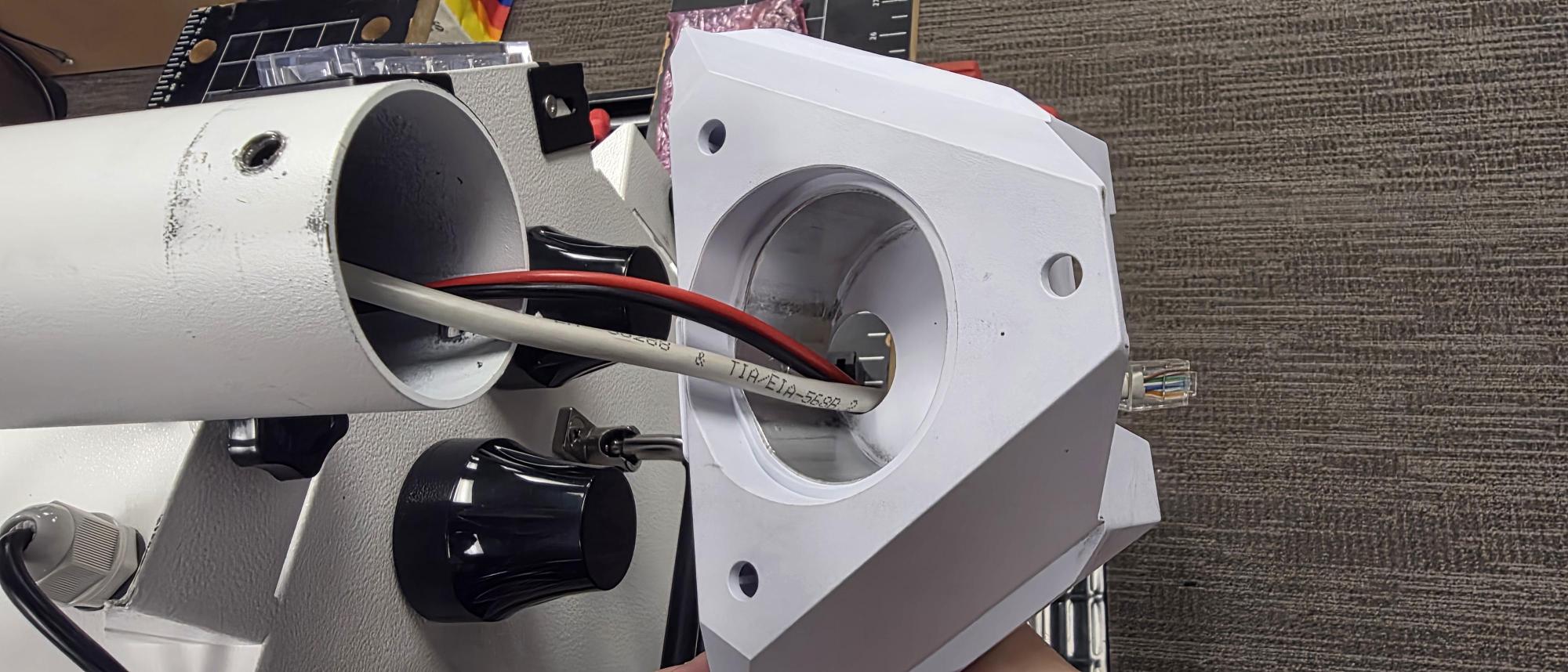
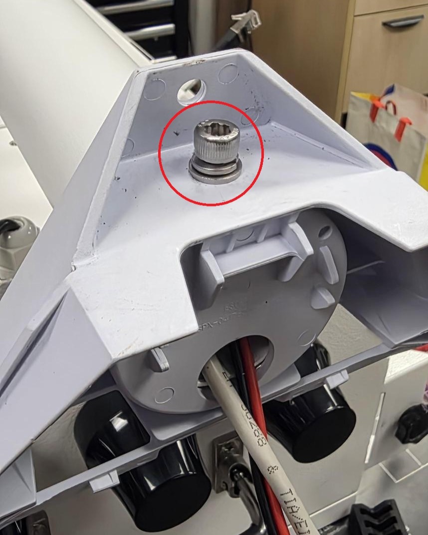
5. Secure the Starlink mounting bracket to the top of the mounting arm using the screw. Ensure the screw passes completely through both holes in the mounting arm and extends through to the opposite side of the mounting bracket.
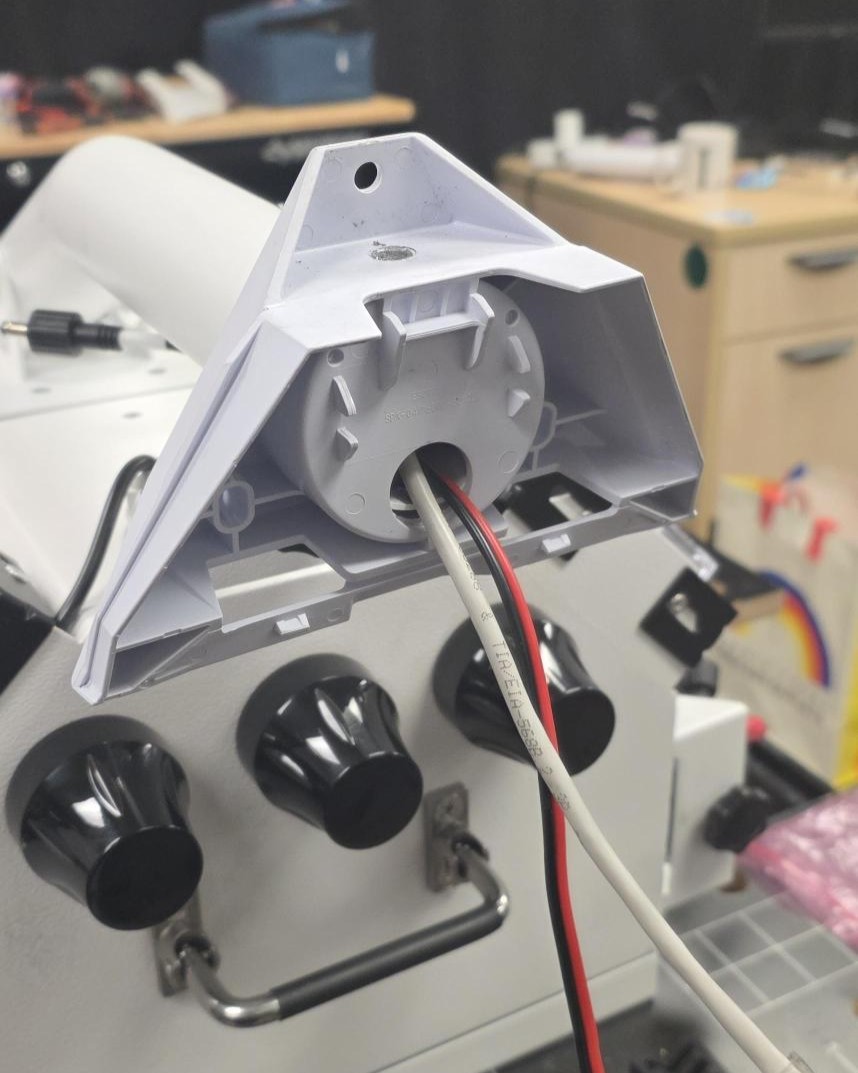
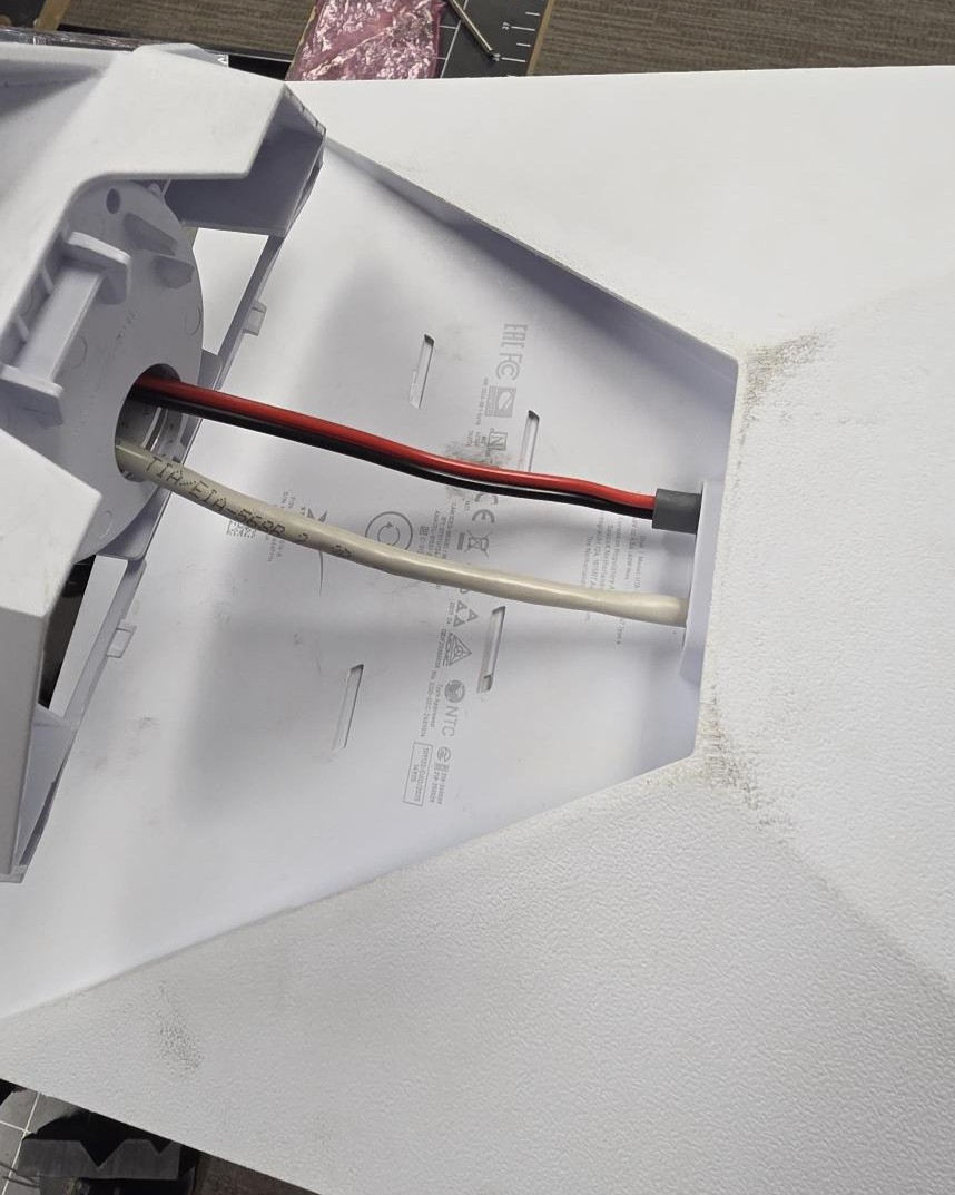
6. Connect the power cable and Ethernet cable to the Starlink unit.
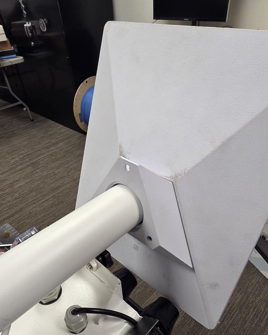
7. Place the Starlink unit onto the mounting bracket until it snaps securely into place.
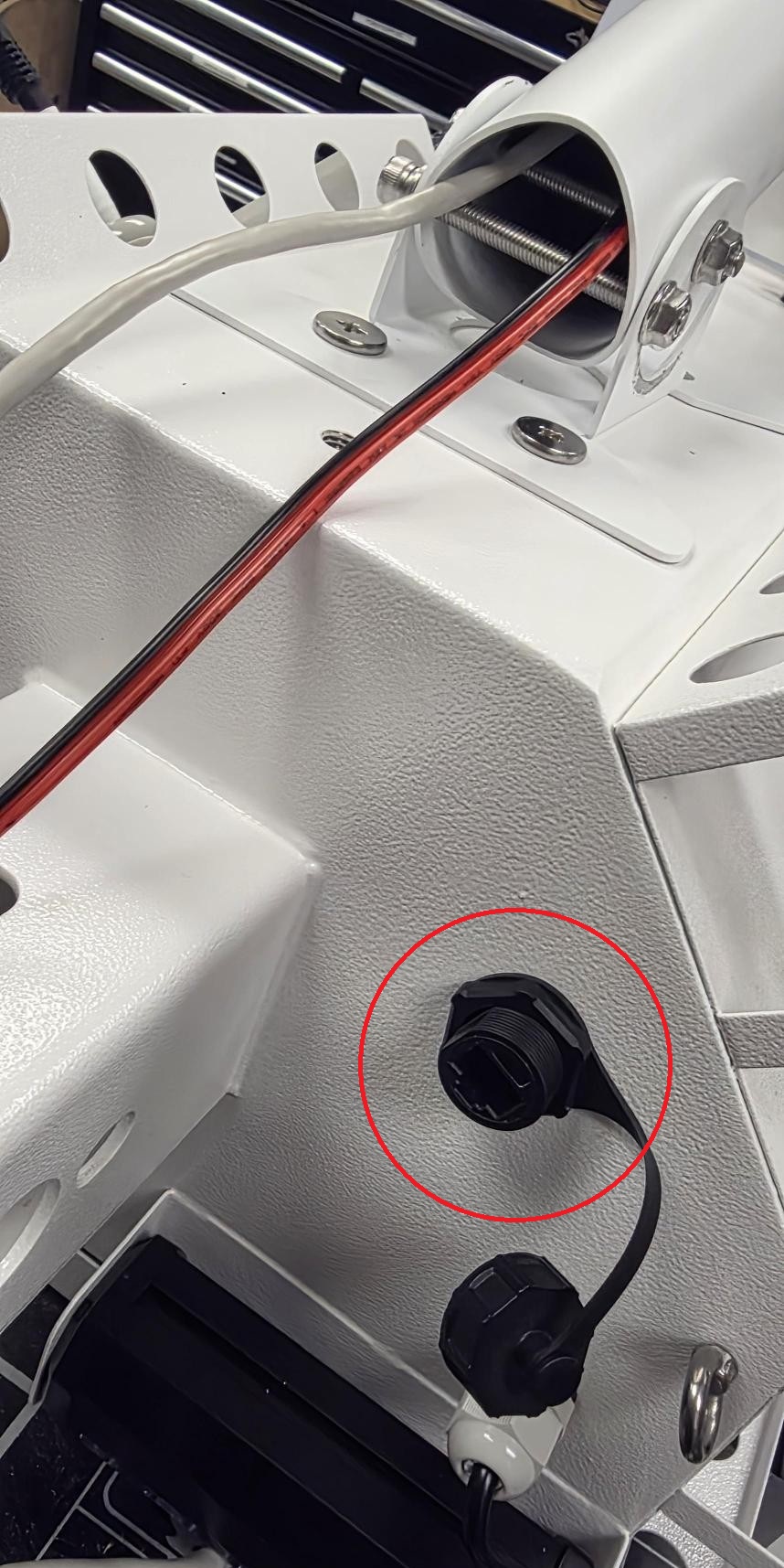
8. At this step, determine the best route for the Ethernet and power cables to enter the control box. For this tutorial, the bottom entry hole will be used as an example.
9. Use a voltmeter to identify the correct 48 VDC polarity for the Starlink power connection.